CNC lathe has precision machining characteristics, improving the machining process’s flexibility and automation.
However, thin-walled parts have low rigidity and limited load-bearing capacity.
As a result, the clamping and cutting forces applied during machining can easily cause elastic and plastic deformation.
This deformation negatively affects machining accuracy and final quality.
The cutting heat generated by friction between the tool and the workpiece during machining raises the part’s surface temperature, causing thermal expansion and thermal deformation.
In addition, the multiple effects of cutting force, cutting heat, and vibration make machining thin-walled parts more difficult.
Therefore, the machining accuracy of thin-walled parts largely depends on the rational design of process parameters.
Optimizing fixture design, tool geometry, and cutting parameters can effectively reduce deformation caused by mechanical forces, heat, and vibration during machining.
With the advancement of CNC machining technology, efficiently processing thin-walled parts while ensuring machining quality and accuracy has become a key challenge in CNC technology.
Characteristics of thin-walled parts and processing difficulties
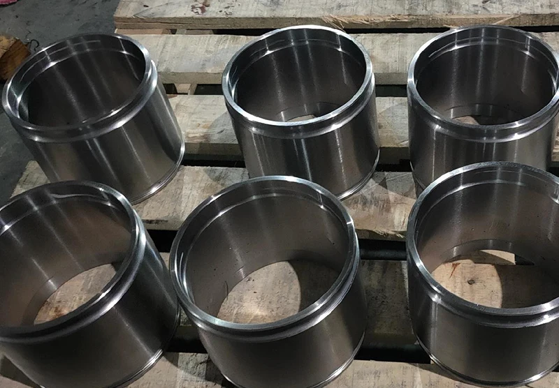
Thin-walled parts refer to components where the ratio of wall thickness to outer diameter is less than 0.05, or the radius of curvature exceeds 20 times the wall thickness.
These parts often feature complex and varied contours and are required to meet high-precision standards.
They are widely used in aerospace and other industries that demand lightweight structures and high strength.
Thin-walled parts in the machining of strong structural vulnerability, once the uneven force is elementary to lead to elastic or plastic deformation.
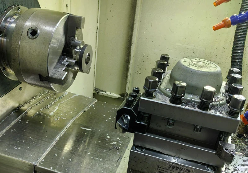
During the clamping process, a three-jaw chuck is used to secure thin-walled parts.
However, if the clamping force is concentrated in a specific area, it can lead to uneven stress distribution on the part’s surface, thereby reducing machining accuracy.
Due to the thin-walled parts’ thin wall thickness, heat is easily concentrated in the cutting area, so the part’s temperature rises sharply.
This triggers plastic deformation, resulting in the part’s shape and size and the design drawings required to produce deviations.
Cutting heat mainly comes from the high-temperature cutting area where the tool contacts the workpiece.
The size of the tool’s front angle, cutting speed, etc., will affect the temperature of the cutting area.
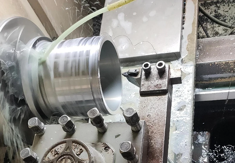
During the machining of long, thin-walled structural parts, the reaction force between the cutting tool and the workpiece often induces periodic vibrations.
This effect is particularly pronounced in low-rigidity thin-walled parts, directly impacting surface quality and machining accuracy.
Usually, the vibration not only affects the surface roughness of the parts but also makes the tool and workpiece resonate, further aggravating the deformation.
Factors affecting the machining accuracy of thin-walled parts
Deformation caused by the force
Thin-walled parts itself has poor structural rigidity, thin thickness, and processing.
If excessive clamping or support force is applied, it can easily cause elastic deformation during the initial stages of machining, directly affecting the part’s final dimensional and shape accuracy.
If the fixture force selection is not appropriate during the clamping process, thin-walled parts are very easy to deform due to uneven force.
If the positioning is not selected properly, the part may be subjected to additional stress, leading to surface deformation.
This can affect the part’s shape, dimensional accuracy, and positional deviation.
In addition, the cutting force generated by the tool’s action will directly lead to local elastic or plastic deformation of the workpiece.
When the feed rate and depth of cut are not set properly, the cutting force is more likely to cause the parts to bend, change shape, and even lead to processing failure.
Deformation caused by heat
During machining, cutting heat generated by the friction between the tool and the workpiece is transferred to the surface layer of the thin-walled parts.
This causes expansion at the atomic or molecular level. However, due to the disproportionate relationship between the heat diffusion area and the part’s volume, the heat cannot dissipate quickly.
As a result, thermal deformation becomes concentrated in localized areas, increasing the likelihood of part warping or shape distortion.
At the same time, thin-walled materials subjected to high temperatures may undergo both elastic and plastic deformation.
After machining, these parts cannot fully return to their original shape during the cooling process, resulting in increased residual stress and exacerbated dimensional deviation.
In addition, due to the thermal expansion effect, the depth of cut of the tool changes during the turning process, resulting in surface ripples and increased roughness.
Due to the uneven rise in temperature, the workpiece’s surface gradually loses its original hardness and elasticity.
The part’s internal structure produces an irreversible fatigue phenomenon.
As a result, the surface quality after processing is lower than the standard, making it difficult to meet the accuracy requirements.
Deformation caused by turning vibration
Thin-walled parts are susceptible to the radial cutting force generated during processing.
The cutting force between the tool and the workpiece results in changes in the shape of the workpiece surface. This makes it difficult to control the machining accuracy.
Especially in the feed direction perpendicular to the horizontal plane, the frequency of cutting force impact easily leads to increased vibration.
This triggers the problem of part deformation.
In thin-walled parts processing, fracture chips will continue to be produced.
The cutting resistance between the tip of the tool and the workpiece constantly changes, resulting in small oscillations in the interaction between the tool and the workpiece.
As a result, the surface of the part cannot be maintained flat.
Under high-speed cutting, the vibration amplitude further increases, which affects the appearance quality of the parts.
It also leads to uneven distribution of internal stress, resulting in increased dimensional error.
Optimized design of thin-walled parts machining
Optimized design of clamps
Thin-walled parts using traditional clamping methods often can not meet the demand for high-precision machining.
Therefore, axial clamping and positioning are generally used to reduce the impact of the clamping force on the part’s deformation.
At the same time, combined with the structural characteristics of the parts and the force situation, the design of special fixtures or multifunctional fixtures, as shown in Figure 1, is necessary.
This ensures that the parts experience uniform force during the clamping process.
The above design ideas are applicable to general thin-walled parts processing and can effectively address the more complex part shape and location requirements.
For thin-walled parts, fixtures in the design should focus on reducing the clamping force’s impact on the thin-walled surface deformation.
The distribution of multi-point clamping around the parts can effectively improve the overall clamping uniformity.
Based on the three-jaw chuck self-centering clamping method, it can more accurately locate the internal and external circular thin-walled parts in the axial position.
Another core of fixture optimization is to reduce the additional deformation caused by vibration and force changes in machining.
Auxiliary washers, balance blocks, or adjustment blocks help bring the fixture’s center of gravity close to the spindle.
This reduces the torque and inertial force interference, and improves the overall accuracy and stability of parts processing.

Selection of tool geometric parameters
Geometric angles, such as the tool’s front angle and the main deflection angle, directly affect the size of the cutting force, the cutting temperature, and the quality of the cutting surfac
The front angle determines the size of the friction in the cutting process.
If the front angle is large, although the cutting deformation tends to be small, the strength of the tool and its heat dissipation performance will be negatively affected.
The lack of strength at the tip of the tool may lead to higher cutting temperatures, which affect the surface quality of the parts and the tool’s lifespan.
If the tool’s main angle and vice-deflection angle are too large, they can reduce the cutting force. However, this will also weaken the tool’s toughness, increasing its wear rate.
As a result, the tool’s thermal performance will deteriorate in high-temperature conditions, affecting its lifespan. Ultimately, this leads to substandard machining accuracy of the parts.
In the processing of thin-walled parts, the main deflection angle is usually selected between 93° and 97° to reduce the impact of force deformation on machining quality.
The vice-deflection angle should be controlled between 8° and 12°, to obtain a better cutting effect.
Reasonable selection of cutting amount
A too-large cutting amount can drastically increase the part force, triggering deformation and even affecting the final surface quality.
Choosing a smaller amount of back draft can reduce the radial force to a certain extent and then inhibit the tendency to deformation.
In practice, roughing can be set at about 0.5 mm to quickly remove excess material.
Meanwhile, in the finishing stage, the amount of backlash should be reduced to 0.25 mm, to ensure that the workpiece maintains a fine surface structure.
In addition, too high a spindle speed tends to aggravate vibration and affect machining stability.
Therefore, in the finishing stage, the spindle speed should be controlled within 1,200 r/min.
This helps avoid vibration and roughness on the machined surface caused by excessive speed.
Feed rate selection should refer to the workpiece material and processing type.
It is recommended to use a 0.1 mm / r feed rate to ensure the material removal speed and maintain the surface machining accuracy of the parts.
CNC lathe processing thin-walled parts parameter optimization
Tool sharpening
Thin-walled parts are susceptible to vibration and thermal deformation during the cutting process. The tool edge needs to be kept sharp,
but it must also have appropriate toughness and wear resistance.
This helps reduce the cutting force and mitigate the impact of the cutting band.
In practice, the tool material is usually selected YT15 cemented carbide, which is good in toughness and wear resistance and suitable for stabilizing the thin-walled finishing stage.
The geometry of the tool’s cutting edge needs to be accurately designed. The main deflection angle should be controlled between 93° and 95°.
The secondary deflection angle should be maintained at about 8°. The front angle should be fine-tuned to around 10° up and down, to maintain sharpness while properly dispersing the cutting heat.
The chamfer radius of the tool tip is generally set to R0.2.
In addition, the tool surface must be free of notches to maintain the straightness of the cutting edge and reduce cutting resistance.
Cutting the dosage selection
Selection of backdraft
The structural characteristics and machining requirements of thin-walled parts dictate that the depth of cut should follow the principle of “moderate is better.”
In the roughing stage, a slightly larger amount of backstroke, such as 0.5 mm, is usually chosen to improve efficiency and remove most of the residual quantity.
However, in the finishing stage, to further reduce the risk of deformation caused by cutting forces during machining, the backstroke amount needs to be moderately reduced to about 0.25 mm.
This helps reduce the additional stress in the part’s thin-walled areas. It also effectively avoids dimensional errors and shape distortions caused by excessive cutting force.
Shape distortion caused by excessive cutting force is effectively avoided.
The backstroke amount for thin-walled parts should consider the workpiece material, wall thickness, rigidity, and other characteristics.
This is especially important in regions with poor rigidity, where deformation of the thin-walled section occurs.
Generally, a backstroke amount of less than 0.5 mm ensures higher stability in the actual machining process.
Selection of spindle speed
Increasing the spindle speed can generally improve productivity. However, for thin-walled parts, high-speed rotation can lead to chattering.
This increases the risk of deformation and affects the surface quality.
To avoid such problems, it is recommended that the spindle speed be controlled at about 1 200 r/min during finishing to ensure smooth cutting.
The spindle speed should be determined by considering the cutting material, machining allowances, and structural characteristics of the parts.
The finishing cutting speed of 120 m/min can serve as a reference.
This helps calculate the appropriate spindle speed range, which can reduce errors caused by vibration during the cutting process.
The spindle speed should not be too high, especially when processing thin-walled parts with small wall thickness and low rigidity.
Otherwise, frequent contact between the tool and workpiece will generate vibration.
This increases the machining surface roughness and makes it difficult to meet the design requirements.
Selection of feed rate
The feed rate should be matched with the nature of the material, tool geometry parameters, but also comprehensively consider the impact of cutting force on the parts.
Studies have shown that a too-high feed rate increases the cutting load, producing excessive radial force in the cutting process.
This can easily lead to deformation of the parts, especially in the region where thin wall thickness is more obvious.
At the same time, although the feed rate is low, it effectively reduces the cutting load.
However, it can cause the temperature to rise due to excessive friction accumulation.
This, in turn, leads to thermal deformation.
Under normal circumstances, a feed rate of about 0.1 mm/r is appropriate for finishing thin-walled parts.
This feed rate helps maintain the stability of the contact between the tool and the workpiece.
It also minimizes force fluctuations during the cutting process. As a result, it ensures the dimensional accuracy and surface finish of the parts.
Workpiece clamping
Bore machining using fixture clamping
A special fixture should be used for precise clamping when machining the bore of thin-walled parts to ensure the clamping force and accuracy of the workpiece.
This ensures that the parts remain stable and accurately positioned during turning.
The three-jaw self-centering chuck is used to fix the fixture firmly on the lathe. The thin-walled parts are placed in the inner hole of the fixture.
The outer edge of the fixture has a threaded design, which helps increase the reliability of clamping.
At the same time, the left side of the fixture bore is designed with a step structure for axial positioning of the thin-walled parts, which further improves the clamping stability.
After the nut is tightened, the thin-walled parts are firmly pressed in the fixture to avoid deflection or vibration during machining.
External round machining using fixture clamping
Due to the poor rigidity of thin-walled parts, they are susceptible to deformation under the influence of external forces.
Therefore, the fixture design needs to consider the distribution and stability of the clamping force fully.
In general, the fixture is fixed on the spindle of the CNC lathe using a three-jaw self-centering chuck.
Then, the thin-walled parts are inserted into the fixture, with the outer circle positioned on top of the washer. The washer is placed on the fixture’s stepped axis.
Then, with the help of the lock nut, the washer is pressed to clamp the thin-walled parts reliably.
This clamping method not only reduces the fixture pressure and prevents local stress concentration on the parts, but it also ensures that all areas of the part remain stable.
As a result, the risk of deformation during the machining process is reduced.
The design should ensure that the outer circle size of the washer is slightly larger than the bore size of the thin-walled part. It should also be slightly smaller than the outer circle size.
This helps prevent axial movement of the parts. Ultimately, it ensures a high-precision clamping effect.
Machining process
In the roughing stage, higher-than-standard cutting parameters should be selected to improve machining efficiency.
According to the requirements of the part drawing, a machining allowance of 3 to 5 mm should be reserved on one side.
If the allowance is too large, roughing segment processing can be used. This can be completed after finishing one section.
Then, the other areas can be gradually processed through semi-finishing or finishing. Further processing can also be done according to the actual demands.
It still adopts the segment processing method in semi-finishing machining and reserves different allowances for different parts.
The machining can be divided into 3 to 4 sections for longer parts. In the first 1/3 of the part, a 0.5 mm margin can be left.
In the middle 1/3 of the part, a 1 mm margin is left. In the last 1/3 of the part, a 2 mm margin is left. If the part has an end face, a 0.5 mm margin can be left on the end face.
At the finishing stage, the allowance for the first 1/3rd of the position is set to 0 mm to ensure dimensional accuracy.
The middle 1/3rd of the position is left with a 0.5 mm allowance for semi-finishing. The rear 1/3rd of the position is left with a 1 mm allowance.
The end faces can be left with a margin of 0.5 mm. During the finishing process, the allowance should be eliminated in each area.
This process will gradually form a “pyramid” structure. The pyramid structure provides sufficient support to ensure machining accuracy.
In the finishing operation of the bore, it is necessary to choose the appropriate clamping method and control the clamping force to meet the requirements of thin-walled parts.
Conclusion
To summarize, thin-walled parts, due to their unique structural characteristics and application scenarios, put forward higher precision and process requirements in CNC lathe machining.
Thin-walled parts are susceptible to thermal, force, and vibration deformation in machining, making dimensional accuracy and surface quality difficult to guarantee.
Conducting a comprehensive analysis of the part structure and the machining environment is necessary to effectively address these problems.
Accurately setting the machining parameters is also essential. Optimizing the fixture design is another key factor.
Additionally, it is important to reasonably adjust the tool geometry and cutting volume. These measures help to reduce the tendency for deformation during the machining process.
At the same time, the clamping method is more critical, not only to ensure the stability of the parts but also to avoid excessive clamping caused by deformation.
To improve the stability of machining, the spindle speed, the amount of back draft, and the feed rate need to be scientifically regulated.
In addition, the sharpness of tool sharpening plays a significant role in finishing quality. An optimized design of the cutting edge can help reduce the accumulation of heat.
It also minimizes fluctuations in cutting force, which improves overall machining accuracy for thin-walled parts.
Therefore, the CNC lathe machining process design for thin-walled parts is not just about simply adjusting processing parameters.
It also requires a deep understanding of the synergistic effects of multiple factors.
Only by fully grasping and applying these process considerations can the machining of thin-walled parts achieve high precision and high quality.
This is crucial for meeting the needs of industrial production.

