The CNC-integrated center frame is a key load-bearing part critical for safe high-speed rail operation.
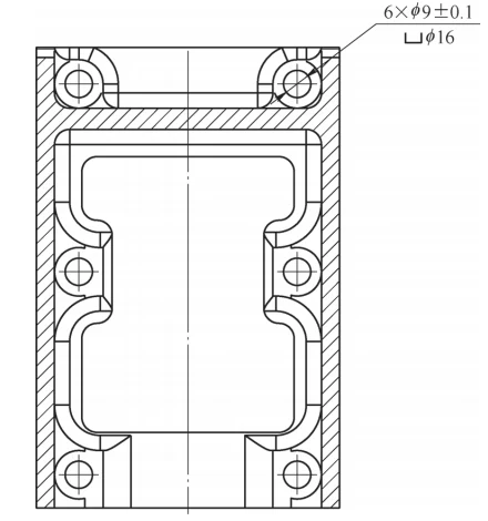
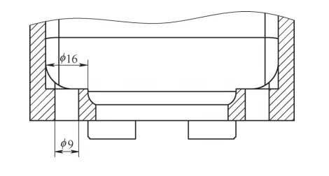
Counterbores in deep cavities (Fig. 1) need EDM, causing long cycles, poor finish, and clamping issues.
CNC milling was adopted for counterbores to replace EDM, cut costs, and boost efficiency.
Problem analysis and process test
Tool type
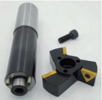
Main counterboring tools include screw-lock (Fig. 2), drive-block (Fig. 3), and eccentric types (Fig. 4).
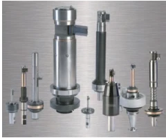
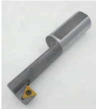
Comparison of various tool machining programs
Screw-lock back-scraper: Extend Z-axis → Lock cutter with screw → Cut upward → Loosen screw, remove cutter → Retract bar to finish.
Advantages: tight installation, sufficient rigidity, replaceable inserts, low cost. The disadvantage is that it takes more time to change the tool.
Clamping and multiple counterbores require screw-lock reverse cutting; rotary cutters aren’t feasible.
Driving block backscraper: block opened by air, lever, taper, collision, or inertia; center frame has φ9mm hole behind countersink.
The φ9mm counterbore uses an automatic BIG back-scraper that closes to pass the hole and unfolds to cut, enabling automated machining.
Machining: Reverse spindle to insert into bottom hole (holder open by centrifugal force); holder folds automatically on contact.
Feed through hole, cut while retracting, then reverse and lift to fold holder and remove.
BIG scraper is efficient, but blade holder damages on front/rear parts (Fig. 5) cause unstable production. Holder shown in Fig. 6.
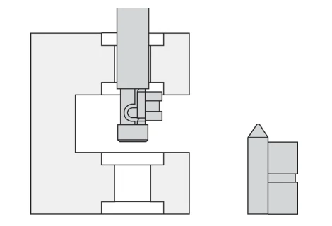
Eccentric counter-scraper requires spindle positioning during tool change to align the blade tip correctly with spindle rotation direction.
Spindle stationary, X-axis shifts >3.5mm to prevent anti-scraper hitting hole wall during milling.
At hole bottom, spindle pauses axially while scraping; the number of rotations (spindle speed × pause time) must be an integer.
Fig. 7–8: anti-scraper trial/tool. Steps: position → eccentric shift → depth → restore → cut → position → shift → retract.
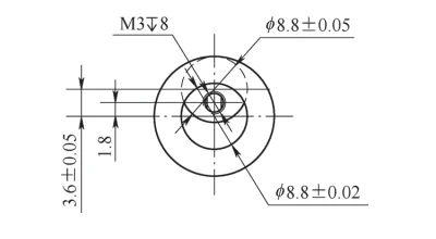
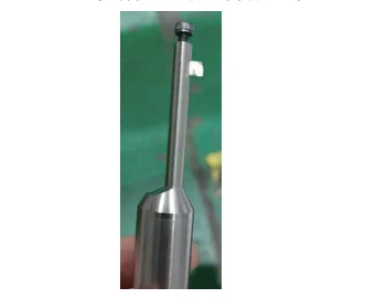
This method avoids spindle reversal, reducing damage risk and manual tool changes, enabling one-step hole processing.
Supports larger counterbores with alloy steel, carbide, or tungsten; needs machine with directional stop.
Improved machining program
φ16mm countersink uses offset eccentric scraper (Fig. 9) on CNC with spindle stop to clear φ9mm holes.
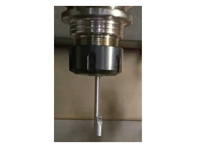
Counter-scraper moves to hole center, pauses to improve finish, then backs up and ends machining.
The machining program is as follows.
N1 G90G54G00X3.6Y0.0; the counter-scraper moves quickly in the X-axis off the hole
Center 3.6mm
N2 G43Z180.0H06
N3 Z115.0
N4 X0.0S280M03; counter scraper returns to hole center
N5 C0lZ125.0F36
N6 G04P450; pause 0.45s to scrape bottom surface
N7 G00 Z115.0 M05
N8 M19; spindle circumferential positioning
N9 X3.6
N10 G91 G28 Z0
N11 G49 G28 XO YO
Conclusion
Verification proves the improved program with eccentric back-scraper is effective and expands deep-hole machining solutions.

