Introduction
In precision engineering, every feature of a component serves a purpose—none more subtly yet crucially than the blind hole. A blind hole is defined as a hole drilled or machined into a workpiece that does not penetrate completely through the material.
While this may seem like a minor design element, blind holes play a pivotal role in optimizing component strength, aesthetics, and functionality.
Blind holes are integral to countless industries including aerospace, automotive, electronics, construction, and industrial machinery, enabling secure fastenings, preserving surface integrity, and supporting confined-space assemblies.
Types of Holes in Engineering
Understanding the types of holes used in manufacturing is essential for proper design and assembly.
Blind Hole: Terminates at a specific depth within the workpiece.
Through Hole: Extends completely through the material.
Other common variations include:
Countersink: Tapered opening for flush screw heads
Counterbore: Flat-bottomed recess to seat bolt heads
Spotface: Machined surface for bolt seating
Tapered Hole: Conical shape for press fits or tapered fasteners
Reamed Hole: Finely machined for tight tolerance fits
Characteristics and Design Considerations of Blind Holes
| Characteristic | Description |
|---|---|
| Depth | Should match thread engagement or fastener length, considering tap chamfers |
| Diameter | Must align with drill and tap specifications |
| Surface Integrity | Maintains exterior surface finish and appearance |
| Accessibility | Limited access complicates chip removal and inspection |
| Tolerance & Finish | Vital for tight fits, sealing surfaces, or stress distribution |
Design Tips:
Include extra depth for chip accumulation beyond the threaded portion.
Avoid intersecting features that could weaken the wall or cause tool deflection.
For tapped holes, ensure thread depth accounts for chamfer loss and usable thread length.
Machining Processes for Blind Holes

a. Drilling Techniques
Hand Drills: Use for low-precision applications; mark depth with tape or depth collars.
Drill Presses: Offer better alignment, depth control, and repeatability.
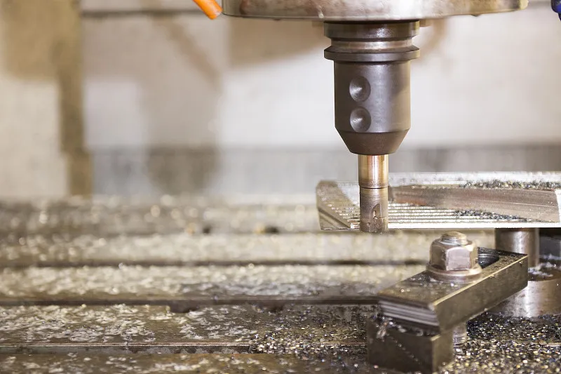
CNC Machines / Lathes: Essential for precise and repeatable hole depths in complex geometries.
Chip Removal is critical:
Use cutting fluids to reduce heat and friction.
Retract frequently to clear chips, especially in deep or narrow holes.
b. Reaming & Finishing
After drilling, reaming enhances hole dimensional accuracy and surface finish. It is especially important for press-fit fasteners or when tight tolerances are specified.
Tapping and Threading Blind Holes
Tap Selection
Spiral Flute Taps: Ideal for blind holes; evacuate chips back out of the hole.
Bottoming Taps: Cut threads close to the hole bottom—necessary for maximizing thread engagement.
Roll Taps (Form Taps): Produce threads by deformation, not cutting—generate no chips and reduce clogging.
Drill Bit Sizing
Ensure proper pilot hole diameter (e.g., M10 × 1.5 → Ø8.8 mm drill).
Thread Depth Formula:
Thread Depth = Thread Length + (Thread Pitch × 9)
This accounts for lead-in threads and complete engagement.
Chip Management:
Clean regularly during tapping cycles.
Inspect taps for wear or chip build-up.
Fasteners Suitable for Blind Holes
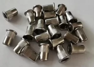
a. Standard Blind Rivets (e.g., ALFO Type)
Features: Expand inside the hole; grooved shafts ensure grip.
Applications: High-retention assemblies with access from one side only.
Installation Guidelines:
Experiment to determine proper drill size.
Rivet length should exceed part thickness and accommodate mandrel head.
Validate pull-out resistance through testing.
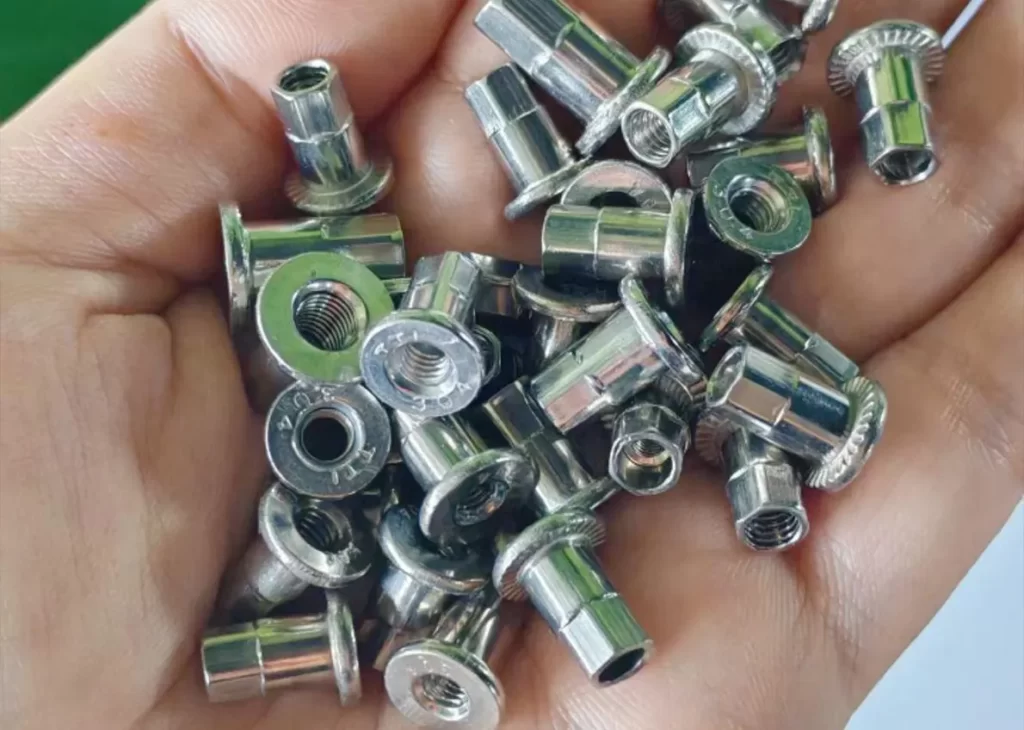
b. Hammer Drive Blind Rivets
Installation: Set by hammer impact; no special tool required.
Material Compatibility: Usable with steel, aluminum, and plastics.
Applications: Building cladding, enclosures, sheet metal frames.
Tip: Trial fitting is essential to determine suitable length and hole tightness.
Blind Hole Symbol and Technical Callouts
In engineering drawings, blind holes are depicted using a circle with a partial centerline and depth arrow. Example:
M6 x 1 ↧12 / 16
Thread: M6 x 1
Thread Depth: 12 mm
Total Hole Depth: 16 mm
This ensures machinists and quality inspectors understand both the usable thread and full drill depth.
Cleaning and Inspection of Blind Holes
Debris Removal Methods
During Machining:
High-pressure coolant
Peck drilling with fluid flush
Post-Drilling:
Compressed air
Vacuum nozzles
Nylon brushes for manual cleaning
Inspection Tools
Depth Gauges and Dial Indicators for depth validation
Borescopes and optical probes for visual inspection
Non-destructive methods for critical or internal holes
Applications of Blind Holes
Mechanical Fastening: Concealed bolt or rivet heads for aesthetic or clearance reasons
Hydraulic Systems: Blind cavities serve as fluid pockets or manifold features
Aesthetic Parts: Prevent visible holes on outer surfaces
Structural Joints: Enable load-bearing fastening without compromising through-part integrity
Blind Holes vs. Through Holes: Summary Comparison
| Aspect | Blind Hole | Through Hole |
|---|---|---|
| Depth | Partial | Full material thickness |
| Tapping Tools | Spiral flute, bottoming taps | Taper taps, spiral point taps |
| Chip Evacuation | Challenging | Easier due to exit path |
| Appearance | Concealed fasteners | Fasteners exposed on both sides |
| Structural Use | Controlled load distribution | Ideal for bolted joints and high loads |
Common Challenges in Blind Hole Machining
Chip Clogging: Leads to tap binding or drill breakage
Depth Overrun: May puncture through thin sections
Access Limitations: Complicated in complex or multi-sided parts
Tool Breakage: Common if retraction or lubrication is neglected
Best Practices & Engineering Tips
Use CNC or drill presses for accurate control
Mark drill depth using collars, stops, or indicators
Always apply lubricants to reduce friction
Pre-drill pilot holes for large-diameter holes
Verify both depth and cleanliness before tapping or assembly
Clean thoroughly to prevent fastener issues or corrosion
Conclusion
Blind holes are foundational to precision component design across numerous industries. Their ability to enable concealed fastening, conserve material strength, and enhance aesthetics makes them indispensable in high-performance assemblies.
However, successfully machining and fastening blind holes demands careful planning, tool selection, and methodical execution.
Selecting suitable fasteners like grooved blind rivets or hammer-drive types, and following best practices, ensures secure, long-lasting assemblies.
Whether you’re designing lightweight aerospace structures or high-volume industrial parts, mastering blind hole strategies is a critical step toward manufacturing excellence.


