

Quick Answers
What is CNC Machining?
CNC machining is a computer-controlled subtractive manufacturing process that removes material from solid stock to produce high-precision metal or plastic parts that meet strict dimensional, functional, and quality requirements.
In modern product development and industrial manufacturing, CNC machining is often associated with a familiar set of challenges: holding tight tolerances without driving costs out of control, translating design intent into manufacturable geometry, avoiding costly rework caused by poor design-for-manufacturing decisions, and selecting reliable suppliers capable of delivering consistent quality on schedule.
These issues directly impact time-to-market, total landed cost, and product reliability.
This guide is written specifically for mechanical engineers, product designers, and sourcing or procurement managers who are responsible for making technical and commercial decisions around precision parts.
By the end of this article, you will understand how CNC machining truly works from an engineering and cost perspective, how to choose the right machining process, and how to design and source parts that reduce cost, shorten lead times, and improve overall manufacturability.
What Is CNC Machining?
CNC machining, or Computer Numerical Control machining, is a subtractive manufacturing process in which pre-programmed digital instructions control machine tools to remove material from a solid workpiece.
Unlike formative processes such as injection molding or casting, CNC machining produces parts by cutting away excess material until the final geometry is achieved.
At the core of CNC machining is the integration of CAD, CAM, and machine control.
Engineers create a three-dimensional CAD model that defines the part geometry.
CAM software then converts this model into toolpaths, specifying cutting motions, feeds, speeds, and tool changes.
These instructions are translated into G-code, the numerical language that CNC machines use to execute precise movements.
Compared to manual machining, CNC machining eliminates reliance on operator hand skills for dimensional accuracy.
Manual machining depends heavily on experience and incremental adjustments, whereas CNC machining delivers repeatability, consistency, and scalability.
Once a program is validated, identical parts can be produced across multiple batches with minimal variation.
Despite the rapid growth of additive manufacturing, CNC machining remains critical for production-grade parts.
CNC-machined components typically offer superior material properties, tighter tolerances, better surface finishes, and broader material availability than most 3D-printed alternatives.
For functional parts, load-bearing components, and tight-tolerance assemblies, CNC machining continues to be indispensable.
How CNC Machining Works (From CAD File to Finished Part)
Digital Design and Programming
The CNC machining workflow begins with digital design. Engineers develop a CAD model that defines all functional dimensions, tolerances, and critical features.
At this stage, design decisions directly affect machining complexity, tool accessibility, and cycle time.
Once the design is finalized, CAM software is used to generate toolpaths.
The CAM system determines how cutting tools approach the material, how much material is removed per pass, and how the part is sequenced through different operations.
Although G-code can be written manually, modern machining relies on CAM-generated code to optimize efficiency and reduce programming errors.
At a high level, G-code instructs the machine on where to move, how fast to move, when to change tools, and how deep to cut.
While the underlying syntax is technical, its purpose is straightforward: translate design intent into controlled machine motion with micron-level precision.
Material Preparation and Fixturing
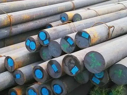
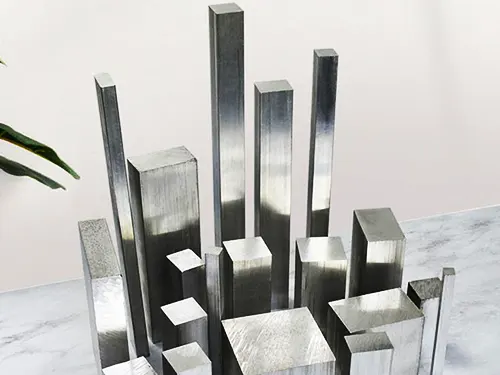
Before machining begins, raw material must be selected and prepared. Common stock forms include plates, rectangular blocks, round bars, and cylindrical billets.
Material choice affects cutting speed, tool wear, surface finish, and cost.
For example, aluminum alloys machine quickly and economically, while hardened steels require slower speeds and more robust tooling.
Fixturing is one of the most critical but often underestimated aspects of CNC machining. Fixtures locate and clamp the workpiece relative to the machine’s coordinate system.
Poor fixturing can introduce vibration, deflection, and misalignment, leading to dimensional inaccuracies or scrap.
Well-designed fixturing ensures repeatable positioning, maintains rigidity during cutting, and minimizes the number of setups required.
Machining Operations and Toolpaths
Machining typically progresses from roughing to finishing. Roughing operations remove the bulk of the material as efficiently as possible, prioritizing material removal rate over surface quality.
Finishing operations then refining critical surfaces, achieve final dimensions, and improve surface finish.
Modern CNC machines perform automatic tool changes, allowing multiple operations to be completed in a single cycle.
Machining strategies such as adaptive clearing, high-speed machining, and trochoidal milling are used to balance tool life, cycle time, and part quality.
Complex parts often require multiple setups, where the part is reoriented to allow access to different features.
Each additional setup increases lead time, labor cost, and the risk of cumulative tolerance stack-up, making setup minimization a key cost driver.
Inspection and Quality Control
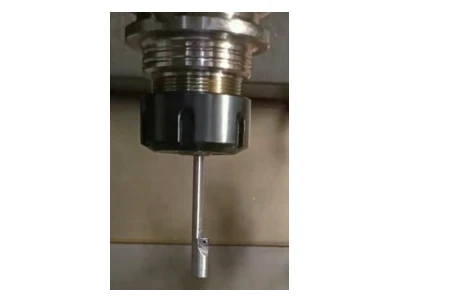
Quality control is integrated throughout the CNC machining process.
In-process inspection may involve probing systems that measure features during machining, allowing for real-time compensation of tool wear or thermal drift.
Final inspection verifies that the part meets all dimensional and geometric requirements.
This may include calipers and micrometers for basic features, coordinate measuring machines (CMMs) for complex geometries, and surface roughness testers for finish verification.
Parts are typically inspected against ISO standards, GD&T specifications, and customer drawings, ensuring compliance with functional and regulatory requirements.
CNC Milling vs CNC Turning — Which Process Should You Use?
How CNC Milling Works
CNC milling removes material using a rotating cutting tool while the workpiece remains stationary or moves linearly.
The machine controls motion along multiple axes, allowing complex geometries to be produced.
Three-axis milling machines move along the X, Y, and Z axes and are suitable for many prismatic parts.
Four-axis machines add rotational movement around one axis, enabling machining on multiple sides without re-clamping.
Five-axis milling provides simultaneous multi-axis movement, allowing complex contoured surfaces, undercuts, and deep cavities to be machined with fewer setups.
Milling is typically used for parts with flat surfaces, pockets, slots, complex contours, and asymmetric geometries commonly found in aerospace, medical, and industrial equipment.
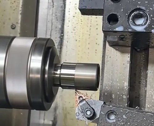
How CNC Turning Works
CNC turning operates on a different principle: the workpiece rotates while stationary cutting tools remove material.
This process is inherently efficient for producing rotationally symmetric parts.
Turning excels at producing shafts, bushings, pins, threaded components, and cylindrical features.
Because material removal is continuous and balanced around the rotational axis, turning often achieves excellent surface finishes and tight concentricity at lower cost than milling.
In many cases, features that could be milled can be turned more economically if the geometry allows.
Selecting turning over milling when appropriate is one of the most effective ways to reduce CNC machining cost.
CNC Milling vs Turning: Decision Table
| Criteria | CNC Milling | CNC Turning |
|---|---|---|
| Geometry | Prismatic, complex, asymmetric shapes | Rotationally symmetric parts |
| Cost Efficiency | Higher for complex non-round features | Lower for round or axial parts |
| Precision | Excellent for complex tolerances | Excellent for concentricity and roundness |
| Typical Lead Time | Longer for multi-setup parts | Shorter due to simpler setups |
| Surface Finish Quality | Very good, toolpath-dependent | Typically superior on cylindrical surfaces |
3-Axis vs 5-Axis CNC Machining (Capabilities and Trade-Offs)
Three-axis CNC machining remains the most widely used configuration in precision manufacturing due to its simplicity, availability, and cost efficiency.
In a 3-axis setup, the cutting tool moves along the X, Y, and Z linear axes, while the workpiece remains fixed in orientation. This inherently limits tool access to features that are reachable from a single direction.
As a result, complex geometries often require multiple setups, part re-clamping, or secondary operations, each of which introduces additional labor, time, and the potential for cumulative error.
Five-axis CNC machining overcomes these access limitations by allowing simultaneous movement along three linear axes and two rotational axes.
This enables the tool to approach the part from virtually any angle in a single setup.
The most significant benefits of 5-axis machining include the ability to machine complex contours, deep cavities, and undercut features; improved surface finish due to optimal tool orientation; and tighter overall accuracy because fewer setups reduce tolerance stack-up.
However, these advantages come with trade-offs. Five-axis machines are significantly more expensive to acquire and operate, and programming complexity is substantially higher.
CAM programming requires greater expertise, and machine time is billed at a higher hourly rate.
For simple prismatic parts or components with features accessible from standard orientations, 5-axis machining often provides no economic benefit.
Five-axis machining is justified when part geometry would otherwise require multiple fixtures, when surface continuity is critical, when tight positional tolerances must be maintained across multiple faces, or when part consolidation can eliminate downstream operations.
It is unnecessary for straightforward components where 3-axis machining can achieve all functional requirements efficiently and at lower cost.
CNC Machining Tolerances and Precision Explained
Standard CNC Tolerances
In most CNC machining operations, parts are produced to default tolerances unless otherwise specified.
Typical shop-standard tolerances range from ±0.1 mm to ±0.05 mm for general dimensions, depending on material, part size, and process capability.
These tolerances are sufficient for many non-critical features and help keep machining costs under control.
ISO 2768 is commonly used to define general tolerances for dimensions and geometrical features that are not individually specified on a drawing.
It provides tolerance classes ranging from coarse to very fine, allowing engineers to communicate acceptable variation without over-dimensioning the part.
This standard is widely adopted in metric-based designs and international manufacturing.
Differences between metric and imperial systems also influence tolerancing practices.
Metric designs typically use nominal dimensions with general tolerances applied, whereas imperial designs often specify explicit tolerances on each dimension.
Understanding the supplier’s default standards is essential to avoid mismatched expectations.
Tight Tolerances and Cost Impact
Tighter tolerances directly increase CNC machining cost because they demand greater control at every stage of production.
Achieving tight tolerances often requires slower cutting speeds, additional finishing passes, temperature control, frequent tool changes, and enhanced inspection procedures.
Each of these factors increases cycle time and labor content.
Tolerance stack-up becomes particularly important in assemblies where multiple parts interact. Even if individual features meet their specified tolerances, cumulative variation can cause functional issues.
Engineers must consider how tolerances interact across mating components rather than treating each feature in isolation.
Over-specification is a common source of unnecessary cost and delay.
Specifying tight tolerances on non-functional features forces suppliers to apply precision processes where they are not needed, increasing lead time and quote price.
Clear identification of critical dimensions helps machining partners allocate resources efficiently.
GD&T vs Linear Tolerances
Geometric Dimensioning and Tolerancing (GD&T) focuses on controlling the functional relationship between features rather than relying solely on linear dimensions.
Instead of specifying tight size tolerances everywhere, GD&T defines allowable variation in form, orientation, position, and runout relative to datums.
When applied correctly, GD&T often improves manufacturability.
It allows machinists to focus on what truly matters for part function, such as concentricity, flatness, or perpendicularity, while relaxing non-critical dimensions.
This approach reduces unnecessary constraints and can lower overall cost while improving assembly performance.
GD&T is particularly valuable for complex assemblies, rotating components, and parts requiring precise alignment.
However, improper or excessive use of GD&T can create confusion and inspection challenges, underscoring the importance of applying it with clear functional intent.
CNC Machining Design Guidelines (DFM Best Practices)
Tool Accessibility and Geometry Limits
CNC machining is constrained by cutting tool geometry. Internal corner radii are a direct result of tool diameter, as end mills cannot produce perfectly sharp internal corners.
Designing internal corners with radii that match standard tool sizes reduces the need for small, fragile tools and lowers machining time.
Tool diameter also limits feature size and depth. Narrow pockets or deep cavities require smaller tools, which are more prone to deflection and breakage.
As depth increases relative to tool diameter, machining becomes slower and less stable, increasing cost and risk.
Reach limitations must be considered for deep features. Long-reach tools amplify vibration and reduce accuracy. Designing parts with reasonable depth-to-width ratios improves stability and surface quality.
Wall Thickness and Feature Stability
Minimum wall thickness depends on material and part geometry. For most metals, wall thicknesses below 1.0 mm increase the risk of vibration and deformation during machining.
Plastics generally require thicker walls due to lower stiffness and higher thermal sensitivity.
Thin walls and delicate features are susceptible to deflection under cutting forces, leading to dimensional inaccuracies and poor surface finish.
In extreme cases, parts may warp after machining due to residual stresses. Uniform wall thickness and gradual transitions help maintain stability.
Holes, Threads, and Slots
Hole depth-to-diameter ratio is a key design consideration. Ratios beyond 5:1 increase drilling difficulty and reduce accuracy, while ratios above 10:1 often require specialized tooling and secondary operations.
Designing shallower holes where possible reduces cost and improves reliability.
Threads can be produced by tapping, thread milling, or single-point turning.
Thread milling offers greater flexibility and lower breakage risk for hard materials, while tapping is faster and more economical for standard threads in softer materials.
Slots should be designed with widths that correspond to standard cutter sizes.
Extremely narrow slots require small tools, increasing machining time and risk of tool failure.
Design Optimization for Lower Cost
Reducing the number of setups is one of the most effective ways to lower CNC machining cost.
Parts that can be fully machined in one or two setups are faster to produce and more consistent in quality.
Avoiding unnecessarily tight tolerances on non-functional features allows machinists to use more efficient cutting strategies.
Simplifying geometry by eliminating cosmetic features, deep pockets, or complex contours that do not contribute to function can significantly reduce cycle time and quotation price.
CNC Machining Materials and Their Applications
Common CNC Metals
Aluminum alloys are among the most popular CNC machining materials due to their excellent machinability, favorable strength-to-weight ratio, and corrosion resistance.
They are widely used in aerospace, automotive, and electronics applications where weight and cost efficiency are critical.
Stainless steel offers high strength, corrosion resistance, and durability, making it suitable for medical devices, food-processing equipment, and industrial components.
Its lower machinability compared to aluminum increases tool wear and machining time.
Brass machines easily and provides excellent surface finish, making it ideal for fittings, connectors, and decorative components.
Titanium combines high strength with low weight and exceptional corrosion resistance but is difficult to machine and costly, limiting its use to high-performance applications.
CNC Machining Plastics
ABS is commonly used for housings and enclosures due to its toughness and ease of machining. Nylon (PA) offers high strength and wear resistance but can absorb moisture, affecting dimensional stability.
POM, also known as Delrin, provides excellent machinability, low friction, and tight tolerances, making it suitable for precision plastic components.
Selecting plastics requires balancing mechanical performance, thermal stability, chemical resistance, and machining behavior.
Material Selection by Industry
Aerospace applications prioritize high-strength, lightweight materials such as aluminum and titanium, often with stringent traceability and quality requirements.
Automotive manufacturing balances cost, durability, and scalability, frequently using aluminum, steel, and engineering plastics.
Medical devices demand biocompatibility, corrosion resistance, and precision, driving the use of stainless steels and specialized plastics.
Electronics and enclosures focus on lightweight materials, dimensional stability, and surface finish, commonly relying on aluminum and engineered polymers.
How Much Does CNC Machining Cost?
CNC machining cost is driven by a combination of technical, operational, and supply-chain factors rather than a single fixed rate.
Understanding these cost drivers allows engineers and procurement teams to predict pricing more accurately and make informed design and sourcing decisions.
Key Cost Drivers
Material selection has a direct and often significant impact on cost.
Easily machinable materials such as aluminum and brass reduce cycle time and tool wear, while hard or abrasive materials like stainless steel and titanium require slower cutting speeds, specialized tooling, and more frequent tool replacement.
Part complexity influences both programming effort and machining time.
Complex geometries with deep pockets, tight internal radii, or multi-axis features increase CAM programming time, extend cycle time, and may require multiple setups or advanced machine configurations.
Tolerance requirements are another major cost driver. Tight tolerances increase machining time, require additional finishing passes, and necessitate more extensive inspection.
In many cases, tolerance requirements have a greater impact on cost than part size.
Machine type also affects pricing. Five-axis machines command higher hourly rates due to their capital cost, programming complexity, and skilled labor requirements.
For parts that do not require multi-axis access, using a 3-axis machine is generally more economical.
Quantity determines how fixed costs such as programming and setup, are amortized.
While CNC machining is well suited for low to medium volumes, per-part cost decreases as quantity increases—up to a point.
CNC Machining Cost vs Production Volume
For prototyping, CNC machining offers a favorable balance between speed, precision, and cost. Tooling investment is minimal, making it ideal for iterative development and functional testing.
In low-volume production, CNC machining remains competitive, especially when design changes are expected or when multiple variants are required.
The flexibility of CNC allows quick adjustments without new tooling.
CNC machining becomes inefficient at higher production volumes where per-unit cost is dominated by machine time.
At this stage, processes such as injection molding or die casting typically offer lower unit costs despite higher upfront tooling investment.
Practical Cost-Reduction Strategies
Design changes often provide the greatest opportunity for cost reduction. Simplifying geometry, reducing the number of setups, and avoiding unnecessary cosmetic features can significantly lower machining time.
Material alternatives can also reduce cost without compromising performance. Substituting a difficult-to-machine alloy with a more machinable equivalent often yields immediate savings.
Tolerance optimization is one of the most effective strategies. Relaxing tolerances on non-functional features allows faster machining and simpler inspection, reducing both cost and lead time.
CNC Machining Lead Times — What Affects Delivery Speed?
Programming time depends on part complexity and the clarity of design documentation. Well-defined CAD models and drawings reduce back-and-forth communication and accelerate CAM preparation.
Machine availability plays a critical role, particularly during peak production periods.
Highly capable machines such as 5-axis systems are often in higher demand, which can extend lead times.
Material sourcing can become a bottleneck when specialized alloys or certified materials are required. Readily available stock materials typically shorten lead times.
Part complexity and the number of setups directly influence production time.
Parts requiring multiple orientations or secondary operations take longer to complete.
Local manufacturing generally offers faster turnaround due to reduced logistics and communication delays, while overseas manufacturing may provide cost advantages at the expense of longer lead times.
CNC Machining vs Other Manufacturing Processes
CNC Machining vs 3D Printing
CNC-machined parts typically offer superior mechanical strength because they are produced from fully dense, wrought materials. Dimensional accuracy and surface finish are also generally better with CNC machining.
3D printing excels in speed for highly complex or internal geometries and can be cost-effective for very low quantities.
However, printed parts often require post-processing to meet functional requirements.
Cost comparison depends on geometry and quantity.
CNC machining is usually more economical for functional prototypes and low-volume production, while 3D printing may be advantageous for early-stage concept validation.
CNC Machining vs Injection Molding
Injection molding requires significant upfront tooling investment but offers very low unit costs at high volumes.
CNC machining, by contrast, requires little to no tooling and is better suited for low to medium volumes.
Injection molding is ideal for mass production of plastic parts with consistent geometry, while CNC machining provides flexibility for design changes and material selection.
Post-Processing and Surface Finishes for CNC Parts
Post-processing enhances both functionality and appearance. Deburring removes sharp edges and improves handling safety.
Anodizing provides corrosion resistance and aesthetic appeal for aluminum parts. Bead blasting creates a uniform matte finish and removes machining marks.
Powder coating provides durable, decorative finishes to metal parts, while heat treatment enhances mechanical properties, including hardness and strength.
Each post-processing step adds cost and lead time but may be essential for performance or regulatory compliance.
When CNC Machining Is the Best Choice — and When It Is Not
CNC machining is ideal for precision components, functional prototypes, and low to medium production volumes where flexibility and accuracy are critical.
It is particularly well suited for parts requiring tight tolerances, high material performance, and reliable repeatability.
A common misconception is that CNC machining is always the most accurate or cost-effective option.
In reality, alternative processes such as stamping, casting, or molding may outperform CNC machining for high-volume or geometry-specific applications.
Understanding process limitations helps ensure that CNC machining is selected for the right use cases.
How to Choose a CNC Machining Supplier
Technical capability should align with part requirements, including machine capacity, axis configuration, and material expertise.
Quality systems such as ISO certification and documented inspection procedures indicate process control and consistency.
Clear communication and responsive engineering support reduce risk during design changes or tight schedules. Transparent quoting that clearly explains assumptions, tolerances, and lead times helps avoid surprises.
Suppliers that offer design-for-manufacturability feedback provide additional value by identifying cost-saving opportunities early in the process.
Frequently Asked Questions About CNC Machining
CNC machining can routinely achieve tolerances of ±0.05 mm, with tighter tolerances possible depending on geometry, material, and inspection methods.
CNC machining is suitable for mass production only up to a certain volume threshold. Beyond that point, tooling-based processes generally offer lower unit costs.
Delivery speed varies by complexity and supplier capacity, but simple CNC parts can often be produced within days.
Materials such as aluminum alloys, brass, and POM are among the easiest to machine, offering fast cycle times and excellent surface finishes.
Conclusion
CNC machining remains one of the most versatile and reliable manufacturing processes for producing precision parts across a wide range of industries.
By understanding its capabilities, cost structure, design considerations, and limitations, engineers and sourcing professionals can make informed decisions that balance performance, cost, and lead time.
When applied strategically and supported by capable suppliers, CNC machining delivers predictable quality, scalable production, and long-term value in both prototyping and production environments.