How to efficiently machine shaped parts on CNC mill-turn machines?



A method for improving the positional accuracy of drilling based on coordinate measuring machine (CMM) results was proposed and validated.
Through data analysis and practical verification, the hub drilling process was optimized to enhance the positional accuracy of the drill holes.
The hub’s orientation is determined based on the machining center’s drilling program.
When measuring positional accuracy using the CMM, the hub must be positioned and oriented in the same manner and sequence as during drilling.
Multiple measurements are conducted to analyze the distribution patterns of hole positional accuracy.
The coordinate differences between the actual center points of the drilled holes and the theoretical center points are then calculated.
After validation through multiple batches of testing, this method was found to reduce hub hole positional deviation by up to 31.25%.
Without the need to upgrade equipment, it provides a cost-effective solution for improving the positional accuracy of drilling on existing machining centers.
As the axle industry has evolved, some manufacturers have imposed increasingly stringent positional accuracy requirements for hub bores.
In actual production, it is often difficult to ensure that all machine tools meet the positional accuracy requirements specified in the drawings due to aging equipment.
If production is carried out on specific high-precision machining centers, it becomes challenging to maintain production efficiency and reduce processing costs.
Purchasing new machine tools or repairing existing equipment would increase processing costs;
Moreover, since most other products do not require such high positional accuracy, this would result in wasted costs when manufacturing those products.
To address this, this paper proposes and validates a measurement-feedback-based program compensation method.
A coordinate measuring machine (CMM) is used to precisely measure systematic deviations in hole positions.
The deviation values are then statistically analyzed and calculated.
Based on the results, reverse compensation is applied in the machining center program.
This method can significantly improve the positional accuracy of hub holes and increase the yield rate.
As a result, it can meet the diverse needs of different customers.
A certain company’s C008 wheel hub part is shown in Figure 1, with a positional tolerance requirement of 0.20 mm.
Although the positional accuracy of products machined on the company’s existing equipment can be consistently maintained below 0.20 mm, this meets the machining accuracy requirements for the current product.
However, other customers have similar products that require a bolt hole positional accuracy of 0.15 mm.
Such high-precision requirements can only be met by a small number of newly purchased machine tools.
However, these machines are already operating at nearly full production capacity.
As a result, it is difficult to guarantee the timely delivery of customer orders. In addition, labor costs are higher.
To enhance the company’s overall production capacity and product competitiveness, it is necessary to optimize the machining process and unlock the precision potential of the existing equipment.
This approach can meet stricter customer requirements while controlling manufacturing costs.
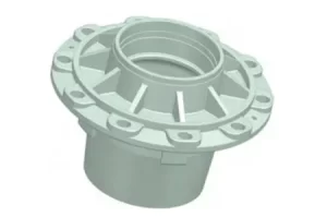
This paper presents a comprehensive process trial to improve the positional accuracy of wheel hub drilling.
The trial consists of four key steps: systematic machining, measurement, data correction, and validation.
The objective is to reduce manufacturing costs while meeting customer requirements.
The main factors affecting the positional accuracy of the C008 hub are the fixture, cutting tools, and equipment.
1) The fixture is used to align the hub center with the workpiece origin on the machining center.
Previously, a mandrel fixture was used. The theoretical maximum positioning clearance between the mandrel fixture and the hub was 0.05 mm.
This clearance significantly affected positional accuracy.
To eliminate positioning errors caused by the fixture, a pneumatic chuck fixture was innovatively designed.
The positioning mandrel was replaced with a high-precision pneumatic chuck.
The centering accuracy of the selected pneumatic chuck fixture is 0.001 mm, making its impact on positional accuracy essentially negligible.
2) The same tool models and brands were used company-wide.
The impact of tools on positional accuracy could not be verified at this stage.
In addition, cutting tools are standardized and have a minimal effect on systematic deviations.
Therefore, the tool brand was kept unchanged throughout the entire testing process. This ensured consistency in the test variables.
3) Machining centers purchased in different years vary in brand and age.
With identical fixtures and cutting tools, the machine tool represents the greatest variable affecting machining accuracy;
However, machine tools cannot be replaced during their service life.
The effects of the fixture and cutting tools have been controlled or eliminated.
Therefore, the systematic positioning deviation inherent to the machine tool is the core variable addressed in this study.
This test was conducted under normal machine tool maintenance conditions, allowing for more effective verification of the feasibility of this method.
To ensure the consistency and comparability of the measurement data, the C008 hub must be positioned at exactly the same angle during both the drilling process on the machining center and the CMM inspection.
The holes must also be inspected in the same sequence.
The specified positioning angle, drilling sequence, and inspection sequence must be strictly followed by the relevant personnel throughout the test.
This ensures accurate analysis of the measurement results and eliminates measurement errors caused by inconsistencies in the positioning angle.
Since CMM inspection takes a relatively long time, taking too many samples can easily lead to congestion in the inspection line, affecting the efficiency of normal product inspection ;
Conversely, taking too few samples makes it difficult to reflect the stability and fluctuations of data during the machining process.
To balance inspection efficiency and the reliability of product data, this experiment employed small-batch processing in groups of three products throughout the entire process.
This approach allows for the collection of statistically significant sample data. It also helps control the inspection cycle.
As a result, the impact of this experiment on normal production schedules is minimized.
During the tests, both the fixtures and the machine tools remained unchanged, and the theoretical tool life was 150 parts.
To ensure consistency in test conditions and comparability of results, new tools were installed at the start of the tests, and no tool adjustments were made during the first two test runs.
This effectively eliminated the influence of tool-related variables on the test results and ensured the reliability of the data.
The C008 hub is a rotary part. During machining, the part must be positioned according to the test requirements.
This ensures that the sequence of drilling and CMM measurements remains consistent throughout the entire test process.
As a result, data accuracy is guaranteed and a reliable basis is provided for subsequent error analysis and program compensation calculations.
To ensure strict control throughout the entire testing process, workshop managers trained machine operators and quality inspectors according to the test specifications.
The training ensured that all personnel fully understood the test plan and procedures.
After the initial inspection on the coordinate measuring machine (CMM) was completed on the same day, machining and inspection were carried out in accordance with the test requirements and procedures.
Dedicated personnel monitored and verified the entire machining and inspection process.
This ensured the authenticity and validity of the data from the first part to the last throughout the entire test.
The C008 hub part has a total of 12 holes. The CMM positional accuracy test results for Hole 1 are shown in Table 1.
This table reveals dimensional deviations between the actual and theoretical positions of the hole in terms of polar radius and polar angle.
Based on these deviations, the machining program can be adjusted in reverse by modifying the polar radius and polar angle values in the drilling program coordinates.
Program compensation values are then applied.
This approach verifies the feasibility of improving drilling positional accuracy through reverse program compensation.
| Element | Theoretical Value | Upper Deviation | Lower Deviation | Measured Value | Deviation |
|---|---|---|---|---|---|
| Polar Radius / mm | 167.5 | — | — | 167.542 | 0.042 |
| Polar Angle / (°) | 0 | — | — | 0 | 0 |
| Feature Size / mm | 23 | 0.2 | 0 | 23.002 | 0.002 |
| Position Degree / mm | Maximum Material Requirement | 0.2 | 0 | 0.084 | 0.084 |
Table 1. Results of coordinate measuring machine position measurement for Hole 1
Coordinate measuring machine (CMM) inspections require a considerable amount of time.
If too many samples are inspected, congestion will occur on the inspection line.
Conversely, if too few samples are inspected, the stability of the machining process cannot be adequately verified.
Therefore, samples are grouped in sets of three throughout the entire testing process.
This test was divided into four batches, with three pieces in each batch. The first batch represented the initial machining run.
After adjusting the program based on the results of the first batch, the second batch was inspected.
If the inspection results for the second batch showed a significant improvement in positional accuracy, the cutting tools were replaced every two days.
The third and fourth batches were then inspected to verify the positional accuracy after the tool changes.
This confirmed the stability of positional accuracy following tool replacement.
Select the C008 product and switch the fixture to a pneumatic chuck fixture, thereby improving centering accuracy to 0.001 mm.
The positional accuracy requirement for this product is 0.20 mm, which all machine tools within the company can meet.
Based on this, verify the feasibility of stabilizing positional accuracy at <0.15 mm through program compensation.
After passing the initial inspection, operators are required to machine three parts in accordance with the test requirements.
The three parts are then submitted to the quality inspection department’s CMM laboratory for inspection.
Upon completion of the inspection, quality control personnel will send the inspection report to the test personnel.
The positional accuracy test results for the first batch of three products (Nos. 1–3) are shown in Figure 2.
For some parts, the positional accuracy of holes 7, 8, and 12 exceeded 0.15 mm, with a maximum value of 0.16 mm.
Figure 3 shows the positional accuracy deviation graph for the first batch of products.
When the positional accuracy deviation is significant, the offset distances and directions of each hole relative to the theoretical hole are consistent.
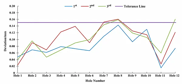
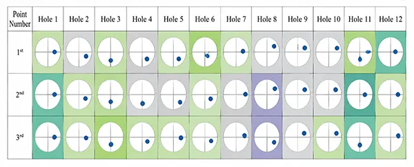
Table 2 presents a statistical analysis of the inspection results for Hole 7.
It examines the actual values, average values, and error values of the polar radius and polar angle relative to the machining center program, as measured by the coordinate measuring machine (CMM).
| Item | Polar Radius / mm | Polar Angle / (°) | Position Degree / mm |
|---|---|---|---|
| 1# | 167.451 | 216.004 | 0.109 |
| 2# | 167.433 | 216.007 | 0.151 |
| 3# | 167.430 | 216.001 | 0.143 |
| Average Value | 167.438 | 216.004 | 0.134 |
| Program Coordinate Value | 167.5 | 216 | — |
| Error | 0.062 | -0.004 | — |
| Optimized Coordinate Value | 167.562 | 215.996 | — |
Table 2 Statistical Analysis of Detection Results for Hole 7
As shown in Table 2, the average error in the actual pole radius for Hole 7 is 0.062 mm, and the error in the pole angle is −0.004°.
The coordinate values in the machining program for Hole 7 were adjusted to a pole radius of 167.562 mm and a pole angle of 215.996°.
The same analytical method was applied to all remaining holes to calculate their error patterns and optimize the compensation machining programs.
After the test personnel finished adjusting the optimized program, they renamed it, imported it into the machining center’s CNC system, and called up the new program to begin machining.
To avoid batch scrap caused by programming issues, the new program was used only after it passed the initial inspection.
Two additional parts were then machined. Afterward, the system was switched back to the original program.
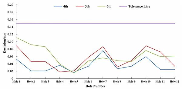
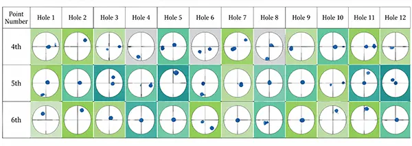
The positional accuracy test results for the three products in the second batch (Nos. 4–6) are shown in Figure 4.
The graph of hole positional accuracy deviations is shown in Figure 5.
The maximum positional accuracy deviation was significantly reduced from 0.16 mm to 0.11 mm—a decrease of 31.25%.
The optimization results were highly significant, fully validating the effectiveness of the program compensation strategy.
To systematically verify the feasibility and stability of this program-based compensation method and ensure machining quality, operators were required to change the cutting tools according to the test requirements.
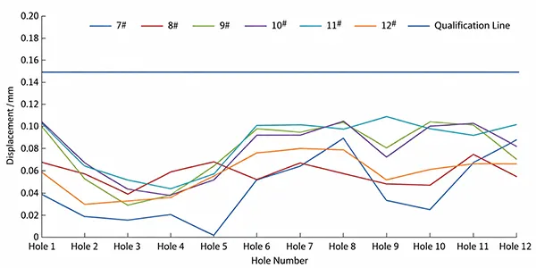
They then conducted machining tests on the third and fourth batches of products (Nos. 7–12) at the specified intervals.
The positioning measurement results are shown in Figure 6, with the maximum positioning error remaining stable at less than 0.11 mm.
This indicates that even after tool changes, this method continues to reliably improve positional accuracy, demonstrating good repeatability and practicality.
This paper presents a method for improving the positional accuracy of drilling on machining centers based on coordinate measuring and program compensation.
This method involves systematically machining the workpieces and measuring the actual hole position coordinates.
The results are verified through multiple rounds of testing. The systematic deviations from the theoretical positions are then analyzed.
Finally, the coordinate values of the relevant holes in the CNC program are corrected to achieve reverse coordinate compensation.
This method can reduce positional accuracy deviations in hub holes by up to 31.25%, with stable and reliable results.
This method does not require upgrades to the machine tool or changes to the cutting tools.
It significantly improves the machining quality of existing equipment while maintaining the machining efficiency of standard products.
At the same time, it avoids the additional costs associated with purchasing new equipment.
This method is primarily suitable for optimizing the positional accuracy of rotary parts and offers good cost-effectiveness and practicality;
However, its applicability to asymmetric or structurally complex parts requires further study.
This method can be widely adopted in similar products and processes, helping to enhance the market competitiveness of a company’s products.

