How to efficiently machine shaped parts on CNC mill-turn machines?



New energy vehicles have achieved rapid development. This trend puts forward higher requirements for component lightweighting and high power density.
It also demands greater precision and reliability for key safety components, including chassis and steering systems.
This trend promotes the upgrading of key automotive components with more complex geometric structures.
Traditional machining methods can hardly satisfy the processing requirements of these parts anymore. Multi-axis CNC technology is represented by five-axis simultaneous machining.
Compared with traditional machining methods, it effectively improves the machining precision and efficiency of complex automotive components.
Therefore, it serves as an advanced machining approach. This technology allows the CNC system to control multiple axes at the same time.
It enables the cutting tool to carry out continuous machining under an optimal orientation. In the end, various complex and precision components can be machined.
Its core advantage lies in the ability to complete multi-surface or even all machining operations with a single setup, thereby eliminating setup errors at the source;
It is particularly well-suited for high-precision machining of complex spatial surfaces.
Consequently, multi-axis CNC technology is currently widely applied in the machining of critical automotive components such as engines, chassis, and drive motors.
This paper first outlines the basic principles and key advantages of multi-axis CNC machining.
This study builds on the above foundation. It conducts an in-depth analysis of the core technologies for high-efficiency and high-precision machining.
The analysis mainly focuses on tool path planning, error compensation, and process monitoring.
Subsequently, using typical automotive component machining case studies, the paper details the application models and practical results of this technology.
Multi-axis CNC machining is developed from the traditional three linear axes, namely X, Y and Z.
At least one rotational axis like the A, B or C axis is added to the system.
It supports simultaneous motion of multiple axes.
This function can precisely control the relative movement between the cutting tool and the workpiece.
Currently, five-axis simultaneous machining is the most technically mature and widely applied method in the manufacturing of complex parts.
Its basic principle relies on a Computer Numerical Control (CNC) system.
The system interprets machining programs. It drives each axis to move precisely through servo motors.
This allows the cutting tool to follow continuous and coordinated motion paths relative to the workpiece in three-dimensional space.
Finally, precision machining of complex surfaces can be realized.
Based on equipment structure, mainstream five-axis CNC machine tools can be divided into two major categories (Figure 1):
One type is the dual-tilt-head configuration, in which both rotary axes are mounted on the spindle head, allowing the tool to tilt in multiple directions.
This is suitable for machining large, heavy workpieces, such as large engine casings;
The other is the swivel-head-plus-rotary-table or dual-rotary-table type, in which the workpiece table handles the rotational movement.
This configuration is more suitable for batch machining of small and medium precision parts.
Typical examples include steering knuckles and brake calipers.
It supports machining five surfaces except the bottom face within a single clamping setup.
While different structural configurations have their own applicable process ranges, their core objective remains the same:
To minimize the number of setups, eliminate positioning errors caused by repeated setups, and improve machining accuracy and efficiency.
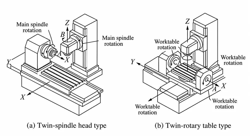
Compared to traditional machining methods, multi-axis CNC machining technology offers the following two core advantages.
1) Exceptional capability to handle complex geometries, which is the most distinctive feature of multi-axis technology.
The tool axis can be controlled flexibly. This effectively prevents tool interference when machining deep cavities and recessed regions.
It supports integrated precision milling of parts with complex spatial surfaces.
Typical workpieces include impellers, turbines, 3D curved surface molds, and monolithic engine cylinder heads.
Such machining tasks are impossible or hard to accomplish using three-axis machine tools.
2) High process consolidation and significantly improved production efficiency.
Multi-axis machines possess multi-surface machining capabilities.
We can take advantage of this feature. Processes including turning, milling, drilling, tapping, and boring can be integrated onto one machine.
These operations formerly needed separate machines and repeated workpiece clamping.
Multi-axis CNC programming and path planning technology adopts computer software.
It generates optimal motion paths for the multiple axes of CNC machine tools.
The planning is carried out according to the workpiece’s 3D model and machining requirements.
Efficient, interference-free, and smooth toolpaths are essential for machining complex automotive components;
Therefore, advanced computer-aided manufacturing (CAM) software and scientific programming strategies are critical.
Three-dimensional CAD models can be used to analyze the process characteristics of the workpiece, thereby enabling the rational division of machining areas and machining operations.
However, it is important to note that when generating toolpaths, the direction of the tool axis must be dynamically adjusted according to changes in surface curvature.
This is to precisely control the tool axis vector and prevent collisions between the tool, the workpiece, and the fixture.
Furthermore, the original toolpath may contain sharp corners or sudden direction changes.
These features can readily trigger a sharp rise in acceleration for the machine tool’s feed axes.
As a result, vibration may occur, and machine tool components may even become damaged.
Therefore, applying algorithms to smooth and filter the toolpath is key to ensuring stable machine tool operation, improving surface finish quality, and protecting the machine tool’s transmission components.
The sources of machining errors are complex and primarily include machine tool geometric errors, thermal errors, force-induced errors, and tool wear.
To ensure accuracy, systematic error detection and compensation technologies must be employed.
Static geometric errors are caused by factors such as the straightness and perpendicularity of machine tool guideways, as well as pitch errors in lead screws.
High-precision instruments including laser interferometers and ballbar systems are used to conduct full-travel inspections of the machine tool.
An error model can be built based on the inspection results.
This model is imported into the CNC system for real-time compensation.
The absolute positioning accuracy of the machine tool is thus effectively enhanced.
During prolonged operation, heat sources such as motors, spindles, and friction in guideways can cause uneven thermal deformation of the structure, severely affecting accuracy—particularly in precision machining.
The mainstream approach involves installing thermocouple sensors at critical locations—such as the machine tool’s lead screw nut housing and column—to collect real-time temperature data at key
points at sampling frequencies ranging from several hertz to tens of hertz.
Deformation is then predicted using an established thermal error model (such as a neural network model), and the control system performs dynamic error compensation.
During the cutting process, tool wear causes machining dimensions to gradually change.
By using an online measurement system, a probe performs real-time in-machine inspection of key workpiece dimensions during machining or between operations.
The deviation data is transmitted back to the control system.
The system automatically adjusts the tool compensation values.
A closed-loop control cycle of measurement—compensation—machining is formed. This mechanism continuously guarantees machining accuracy.
Cutting parameter optimization is a dynamic process that involves appropriately adjusting parameters such as cutting speed, feed rate, and cutting depth to achieve optimal machining results.
Appropriate cutting parameters can reduce cutting temperatures, minimize the risk of tool wear and breakage, extend tool life, and lower manufacturing costs.
High-strength steel and aluminum alloys are widely used materials for automotive components.
Design of experiments methods or intelligent optimization algorithms can be adopted.
Typical algorithms include genetic algorithms and particle swarm optimization.
They help find the optimal combination of parameters such as cutting speed and feed rate.
This approach raises machining efficiency and prolongs tool service life.
QT600 ductile iron and high-strength steel parts can be taken as examples.
CBN tools are used for finishing together with minimal lubrication.
The optimized cutting speed ranges from 200 to 350 m/min.
The feed rate is set between 0.05 and 0.2 mm/rev. Critical dimensions can reach a machining accuracy of ±0.005 mm.
Meanwhile, an intelligent monitoring system—which integrates various sensors for force, vibration, and acoustic emission—enables operators to monitor the multi-axis CNC machining process in real time.
The system analyzes real-time monitoring data. It can quickly identify machining anomalies including tool wear, tool breakage and abnormal vibration.
Then it adjusts cutting parameters accordingly. This measure ensures reliable and stable part machining.
Multi-axis CNC machining technology owns the advantages mentioned above.
Therefore, manufacturers widely use this technology to produce key automotive components.
It effectively solves many difficulties existing in traditional machining processes.
Table 1 summarizes the application of multi-axis CNC machining technology in the machining of three typical types of components.
| Component Category | Core Machining Features & Challenges | Technical Support |
|---|---|---|
| Engine Components | High positional accuracy of hole systems; complex curved-surface machining; dispersed processes; significant influence of thermal deformation | Five-axis simultaneous machining enables multi-surface machining in a single setup; thermal error compensation ensures cylinder-bore surface roughness (Ra ≤ 0.4 μm); turn-mill compound machining shortens the crankshaft process chain. |
| Chassis & Brake Components | Multiple mounting surfaces at different spatial angles; tight positional tolerances; high dynamic balancing requirements | Five-axis simultaneous machining handles spatial angular features; in-process measurement and compensation ensure assembly accuracy (±0.005 mm); intelligent toolpath planning enables machining of complex internal cavities. |
| New Energy Vehicle Components | Thin-wall structures prone to deformation; complex deep-cavity channels; machining of lightweight materials | Deep-cavity toolpath planning avoids interference; intelligent monitoring suppresses deformation; process integration improves pallet machining efficiency and rigidity. |
Table 1. Multi-Axis CNC Machining Applications for Typical Key Automotive Components
An engine consists of numerous components, all of which must meet high standards for wear resistance, heat resistance, machining precision, and corrosion resistance.
Multi-axis CNC technology plays a crucial role in machining the high-precision hole systems in engine blocks, such as main bearing bores and camshaft bores.
A horizontal five-axis machining center can machine all hole patterns and planar features on five cylinder block surfaces in a single setup, excluding the bottom clamping surface.
This reduces machining time and the number of setups while improving machining accuracy.
The hole systems demand extremely high precision; even the slightest error can lead to reduced performance or even failure.
Therefore, manufacturers adopt real-time error compensation technology. A laser interferometer measures and calibrates the machine tool’s position.
Meanwhile, the system monitors the tool condition in real time.
It can detect and compensate for errors induced by machine tool thermal deformation, tool wear and other factors.
This guarantees high precision during the whole machining process.
Chassis components are critical to a vehicle’s handling and safety.
The steering knuckle is a critical safety component that connects the wheel to the suspension, featuring multiple mounting surfaces and bushing holes at various spatial angles.
A five-axis machining center can perform this task. The machine can continuously machine the brake caliper mounting surface, wheel hub bearing mounting surface, upper and lower ball joint mounting surfaces, and all related hole patterns.
All these features are completed under one single setup and positioning.
This effectively ensures the relative positional accuracy of each feature, enabling them to meet the positional tolerance requirements specified in the drawings.
The piston bores and oil passages inside aluminum alloy brake calipers feature complex geometries.
Multi-axis machining enables direct drilling of angled holes and efficient milling of complex internal cavities, thereby improving the surface finish of the oil passages and enhancing sealing reliability.
The rapid development of the new energy vehicle industry has brought new challenges to parts machining.
Take the drive motor as an example: the motor housing is typically made of aluminum alloy, featuring complex spiral cooling channels internally and precision bearing chambers and flanges externally.
Multi-axis machining enables efficient milling of the cooling channel cavities and high-precision boring of the bearing chambers, ensuring the motor’s heat dissipation efficiency, sealing performance, and rotor concentricity.
As a large, thin-walled structural component, the battery tray features complex mounting points, reinforcing ribs, and lightweight cavities on its frame.
The use of five-axis machining centers in the manufacturing process makes it possible to complete the machining of all features in a single setup, while also effectively minimizing machining deformation.
For example, the ball cage bell housing—a core component of the transmission system—requires extremely high precision for its internal raceways.
A multi-axis machine tool can integrate with an automatic rotary positioning finishing device.
This reduces the positioning time for each workpiece to less than 3 seconds.
It realizes high-precision and automated machining of the ball cage bell housing.
This paper systematically reviews the research progress on the application of multi-axis CNC technology in the machining of critical automotive components.
It analyzes multi-axis path planning, error compensation and dynamic optimization of the cutting process.
It illustrates the remarkable advantages of this technology.
These advantages apply to high-precision machining of complex parts including engine blocks, chassis components, and new energy electric drive system parts.
The following conclusions are drawn.
1) Multi-axis CNC machining uses multi-axis interpolation to complete multiple or even all machining operations in a single setup.
This fundamentally eliminates repeat positioning errors and ensures the dimensional and geometric accuracy of components.
2) When machining complex features, the combination of intelligent path planning technology and real-time compensation systems effectively reduces manual operation time, thereby significantly improving machining efficiency and consistency.
3) Intelligent monitoring systems identify machining anomalies in real time. Optimized cutting parameters help prevent these issues and extend tool life. Together, these measures maintain consistent component machining quality.

