How to efficiently machine shaped parts on CNC mill-turn machines?



The annular semicircular sealing grooves in coal mining, petroleum, and forestry machinery are critical components that ensure the equipment’s sealing performance and operational stability.
The parts used in these grooves are mostly made of soft, sticky materials, and the machining process involves stringent requirements.
Currently, the industry’s traditional machining method primarily relies on contour machining with carbide ball-nose end mills.
This process results in rapid tool wear, extremely inconsistent tool life, and low machining efficiency, making it a common industry-wide bottleneck that limits the production efficiency of coal mining, petroleum, and forestry machinery, as well as related motor products.
At the same time, excessively long chips generated during machining are difficult to break off.
Not only do they easily scratch the workpiece surface and reduce machining accuracy, but they also clog the machine tool’s chip removal system and disrupt automated production processes, posing serious risks to operator safety and causing damage to machine tools and equipment.
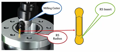
Traditional machining of annular semi-sealed grooves involves contour milling with carbide ball-nose end mills.
Since the outer contour radius of the tool’s ball nose perfectly matches the semicircular radius of the groove bottom, the cutting speed at the tool tip remains zero at all times, preventing the tool from achieving its full cutting potential.
This accelerates tool wear and causes uneven wear distribution, resulting in extremely unstable tool life, significantly increased tool replacement frequency, and persistently high tool consumption costs.
Even when using relatively advanced boring methods to machine annular semicircular sealing grooves, the problem of excessive tool envelope area—due to the groove radius matching the tool radius—remains unresolved, making it extremely difficult to break the chips.
The long, narrow chips generated during machining not only easily scratch the workpiece surface—affecting the product’s sealing performance and operational precision—but also wrap around the tool and clog the machine tool’s chip removal system, disrupting automated continuous production and severely compromising the safety and stability of the production process.
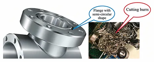
The annular semicircular sealing groove and the chips are shown in Figure 1.
Traditional machining solutions for annular grooves typically use a single-insert design, which limits the amount of material removed per pass and results in low machining efficiency.
More critically, because chip breaking issues cannot be effectively resolved, frequent machine stoppages are required during machining to clear chips, resulting in significant non-cutting time and further reducing production efficiency.
Furthermore, the surface quality of contour machining is determined by the feed rate.
To achieve a higher surface finish on the workpiece, the feed rate must be reduced, which leads to longer machining paths and increased machining time, creating an inherent trade-off between machining efficiency and surface quality that is difficult to resolve.
The traditional method for machining annular grooves is shown in Figure 2.
To address the shortcomings of traditional machining tools—such as their limited versatility, lack of adjustability, and insufficient rigidity—and in consideration of the characteristics of annular groove machining, a new adjustable tooling system has been designed to accommodate the machining of annular grooves of various types and specifications.
Featuring a dual-cutting-edge structure, this system combines high-precision dimensional fine-tuning, high rigidity, and high versatility, providing reliable hardware support for the implementation of the oscillating boring process.
The design drawings and 3D models of the tool system are shown in Figure 3.
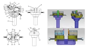
1. Grooving tool holder locking screw; 2. Grooving tool holder locking screw; 3. Size adjustment slider; 4. Round-nose grooving insert; 5. Locating pin; 6. Round-nose grooving insert;
7. Grooving tool holder locking screw; 8. Grooving tool holder (shank type); 9. Grooving tool holder locking screw; 10. Size adjustment slider; 11. Bottom flat surface of the tool holder shank;
12. Slider radial adjustment screw; 13. Main tool body; 14. Slider-to-main-body locking screw; 15. Rectangular locating slot; 16. Scale on the tool body;
17. Scale on the slider; 18. Rectangular locating slot; 19. Slider-to-main-body locking screw; 20. Grooving tool holder (shank type); 21. Slider radial adjustment screw;
22. Elastic slot for locking the grooving insert; 23. Slider-to-main-body locking screw; 24. Slider-to-main-body locking screw; 25. Rectangular locating slot;
26. Rectangular locating slot; 27. Scale on the tool body; 28. Scale on the slider
(1) The main cutting body 13 is directly connected to the machine tool spindle and serves as the reference mounting unit for the entire system; its structural rigidity directly affects cutting stability.
(2) The dimensional adjustment sliders 3 and 10 are mounted on both sides of the main cutter body via a sliding fit.
Their bottoms feature raceway-shaped adjustment grooves 15, 18, 25, and 26, which allow for radial displacement and guide the tool into position.
(3) The slotted grooving tool holders 8 and 20 are embedded within the sliders;
The bottom flat surface 11 of their shanks fits snugly against the contact surfaces of the sliders, forming a stable support surface that prevents twisting during cutting.
(4) The round-tip grooving inserts 4 and 6 are secured within the tool holder slots via a dual mechanism of groove-surface contact and screw clamping;
The edges on both sides of the inserts fit tightly against the slot walls, achieving radial positioning and vibration damping.
(5) The locking mechanism employs a multi-stage, coordinated design.
The tool shank is axially clamped by four sets of locking screws 1, 2, 7, and 9 on the slider; the slider and the main tool body are jointly constrained by four locking screws 14, 19, 23, and 24, along with locating pin 5, to eliminate clearance;
Radial fine adjustment is driven by two sets of adjustment screws 12 and 21, which, in conjunction with the scale markings 17 and 28 on the slider and 16 and 27 on the cutter body, enable high-precision setting.
The tooling system can be equipped with grooving inserts of various shapes according to machining requirements.
It can not only machine semicircular sealing grooves but also accommodate the machining of various types of annular grooves, such as rectangular, trapezoidal, and end-face grooves.
This significantly enhances the tool’s versatility and reduces both the frequency of tool changes and tool inventory costs.
Both the cutter body and the adjustment slider are equipped with precise scale markings.
During installation, align the scale lines 16 and 27 on the bottom surfaces of the round shanks of the two slotting cutter shanks with the scale lines 25 and 26 on the sliding slot to ensure the cutting inserts are in the optimal cutting position.
The radial screws 12 and 21 at the bottom of the adjustment slider allow for precise fine-tuning based on the actual machining dimensions of the part.
To ensure tight tolerances during machining, insert the positioning pin 5 from top to bottom into the circular hole on the main cutter body 13.
By measuring the distance between the pin and the circular cutting edge of the blade, you can accurately calculate the blade’s actual mounting position, thereby achieving precise calibration of the blade’s position.
(1) The main cutter body 13 is mounted directly on the machine tool spindle and serves as the system reference.
(2) The dimensional adjustment sliders 3 and 10 are inserted into the rectangular positioning slots 15, 18, 25, and 26 of the main cutter body and secured with four bottom screws 14, 19, 23, and 24.
(3) The slot-shank grooving tool holders 8 and 20 are inserted into the sliders, with their bottom surfaces 11 resting against the support surfaces of the sliders to prevent rotation.
(4) The round-head grooving inserts 4 and 6 are loaded into the slots of the tool holders, where they are held in place by the slot walls and then secured with screws.
(5) Radial fine adjustment is achieved by pushing the slider with screws 12 and 21; scales 16 and 27 are on the cutter body, while scales 17 and 28 are on the slider for reading.
(6) Insert the locating pin 5 into the corresponding hole to ensure there is no relative displacement between the slider and the main cutter body.
(7) Once all locking procedures are complete, the tool position is stable, and there is no deviation during cutting.
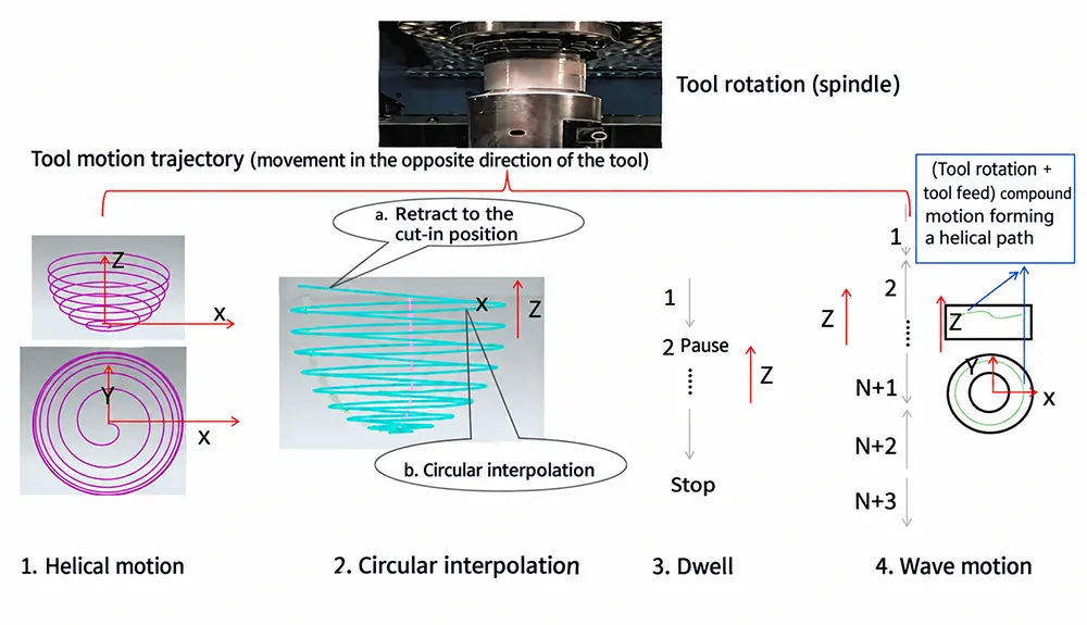
By incorporating principles of wave theory and oscillation theory into traditional boring processes and leveraging the three-axis interpolation capabilities of CNC machine tools, four innovative oscillating boring strategies were developed:
Helical boring, broken-line circular boring, intermittent boring, and wave-type boring.
Through comprehensive comparative testing and theoretical analysis of indicators such as cutting performance, chip breaking effectiveness, programming difficulty, surface quality, and tool compatibility for these four strategies, wave-type boring was ultimately selected as the optimal machining method, achieving the multiple objectives of precise chip control, improved machining efficiency, and guaranteed surface quality.
Helical boring, zigzag circular boring, intermittent boring, and undulating boring all employ oscillating boring and milling processes.
After repeated test cuts and production validation, the undulating boring process was found to offer the best overall performance and was ultimately selected as the oscillating boring and milling method.
It has now been stably applied in the company’s production for nearly a year, yielding significant machining results.
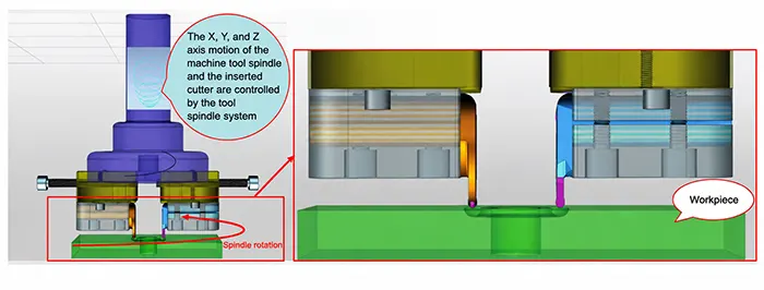
When using this machining process, while the tool rotates, the Z-axis moves back and forth in both positive and negative directions.
For each complete feed and retract cycle, the tool rotates approximately 1.2 revolutions, and the motion continues in a continuous loop.
The insert model used is N123J2-0600 -RO 1125. The “RO” designation indicates a fine-finishing groove profile;
The cutting edge has not been desensitized, resulting in no noticeable resistance during cutting.
The insert surface features a PVD coating, which reduces cutting forces by approximately 15% to 20% compared to uncoated inserts, slows the wear rate, and extends the tool change interval.
No significant vibration occurred during machining; the spindle load remained stable, and there were no abnormal noises.
Tool life was stable; after 8 hours of continuous machining, wear on the rake face did not exceed 0.15 mm.
The advantages of this process include precise control of chip length, which fundamentally solves the problem of chip breakage;
Machining efficiency is more than seven times higher than that of traditional processes;
Programming can be achieved using macro programs, making operation simple;
And the use of an R3 grooving cutter allows for direct machining of R3 semicircular grooves without the need to change specialized tools, while also producing excellent surface quality.
The oscillating boring and milling process is shown in Figure 4.
The oscillating boring process relies on the three-axis interpolation capabilities of a CNC machine tool.
While the machine tool spindle drives a new tool system to rotate at high speed, the three-axis interpolation of the CNC machine tool generates a spherical helical toolpath, enabling efficient boring and milling of annular semicircular sealing grooves.
During the rotational cutting process, the tool performs high-frequency, small-amplitude reciprocating feed movements along the Z-axis.
The machining path is shown in Figure 5.
Through this oscillating cutting method, the chips are subjected to periodic changes in cutting forces and the peeling effect caused by the tool’s retraction during chip formation, thereby achieving precise chip breaking and length control.
This fundamentally resolves the industry-wide challenge of difficult chip breaking encountered in traditional machining processes.
Before optimization, calculations based on the production line balance loss rate formula showed a balance loss rate of 80.52%, far exceeding the industry’s reasonable benchmark of 20%.
Process transitions were disjointed, resulting in significant time waste and constrained production capacity.
Following optimization, the production line balance loss rate dropped to 6.1%, meeting the “Excellent” evaluation standard and achieving highly efficient, balanced production on the line.
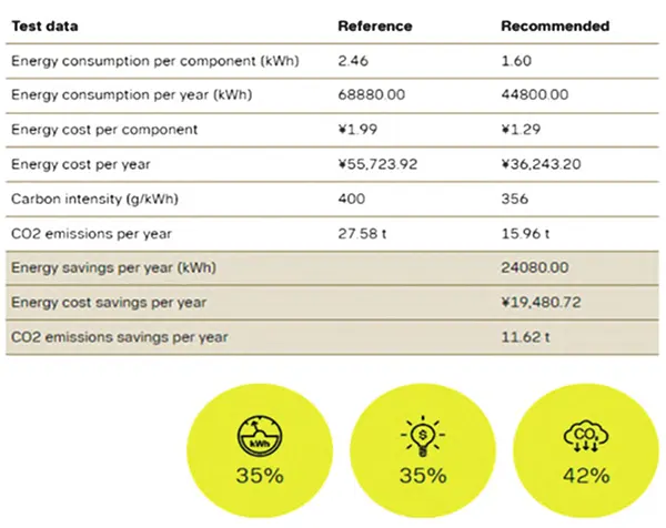
Based on calculations and analyses using the industry-specific software Productivity Analyzer, the pulsed boring process has achieved significant energy savings and carbon emissions reductions by improving machining efficiency, reducing non-cutting downtime, and lowering machine tool energy consumption.
The specific annual benefits are shown in Figure 6.
The application of the oscillating boring process and the new tooling system has reduced manufacturing costs in various aspects, including tool consumption, electricity costs, insert life, and production line efficiency, resulting in significant economic benefits.
The total annual economic benefits amounted to approximately 21,765,877.6 yuan (excluding indirect benefits), with the core benefits outlined below.
(1) Savings on cutting tool costs: The oscillating boring process significantly improves machining efficiency and reduces tool wear.
Annual savings per machine amount to 35.267 yuan per part × 7,000 parts = 246,869 yuan; for 8 machines, the total annual savings amount to 1,979,542 yuan;
(2) Electricity cost savings: The total annual electricity cost savings for the 8 machines amount to 155,845.76 yuan;
(3) Savings from extended insert life: The high-rigidity structure of the new tooling system, combined with the low cutting forces characteristic of pulsed boring, has significantly extended insert life.
According to actual production statistics from the workshop, annual savings on insert costs amount to 41,200 yuan;
(4) Indirect benefits for the production line: By optimizing bottleneck stations and improving production line balance, annual indirect economic benefits amount to 293,760 yuan.
Safety standards have been significantly improved.
Precise control of chip length achieved through the oscillating boring and milling process has completely resolved issues such as long chips scratching operators, scratching workpieces, and damaging machine tools and chip removal systems.
The annual accident rate on the production line has dropped from 0.443% to 0; Product machining quality has significantly improved.
Combined with the precise dimensional control provided by the new tooling system, this has effectively enhanced the machining accuracy and surface quality of annular grooves, reducing the product scrap rate from 9.1% to 0.2%.
The new tooling system and oscillating boring process are primarily suitable for machining various types of annular grooves in coal mining machinery and petroleum equipment.
The core compatible groove types include semicircular sealing grooves, end-face grooves, rectangular grooves, and trapezoidal grooves.
This process is suitable for machining annular groove parts made of various viscous and soft materials and offers broad process adaptability.
Oscillating boring is a ring groove machining process pioneered in China.
It combines tool rotation with Z-axis reciprocating motion, rotating 1.2 revolutions per cycle, with chip lengths ≤50 mm, resulting in no chip entanglement or surface scratches.
Machining efficiency is increased by more than 7 times.
It is suitable for semi-circular, rectangular, and trapezoidal grooves in coal mining machinery and petroleum machinery, without the need to modify the machine tool.
By 2025, the accident rate will be 0, the scrap rate will drop from 9.1% to 0.2%, the groove width tolerance will be ±0.018 mm, and the surface roughness Ra will be ≤1.6 μm.
The cutting tools utilize N123J2-0600-RO 1125 PVD-coated inserts, with wear of ≤0.15 mm/8 h.
This results in reduced electricity consumption, lower operational costs, and less waste, leading to a significant reduction in overall costs.
Process operations are carried out in accordance with SOPs: scales are zeroed, screws are tightened, and parameters remain unchanged.
The process is replicable on-site and can be implemented at low cost.
This study addressed industry challenges associated with traditional machining processes for annular semicircular sealing grooves in coal mining, petroleum, and forestry machinery—including high costs, significant safety hazards, low efficiency, and difficulties in ensuring machining quality.
By integrating lean manufacturing, mechanical oscillation theory, wave mechanics, and metal cutting, this study has completed the optimized design of a novel adjustable tooling system and the innovative development of an oscillatory boring process.
Through repeated test cuts, process optimization, and production validation, the following core conclusions were drawn:
(1) The new tool system features adaptability to multiple groove types, high-precision dimensional fine-tuning, and a high-rigidity structure.
The dual-cutting-edge design significantly enhances machining efficiency, enabling the integrated machining of various types and specifications of annular grooves—including semicircular, rectangular, and trapezoidal—thereby providing reliable hardware support for the implementation of the oscillatory boring process, while offering simple operation and strong versatility.
(2) Among the four innovatively developed oscillating machining strategies—helical boring, broken-line annular boring, intermittent boring, and undulating boring—the undulating boring process offers the best overall performance.
When paired with the N123J2-0600 – RO 1125 PVD-coated inserts, it effectively prevents cutting oscillation while balancing machining efficiency, chip control, and surface finish quality.
(3) This process has a wide range of applications in the machining of annular grooves in industries such as coal mining machinery, petroleum, and forestry machinery.
It significantly improves machining efficiency and offers multiple benefits—including technical, economic, safety, and environmental advantages—providing a highly effective solution for the machining of similar parts in these industries and demonstrating exceptional value for promotion and application.

