

In today’s post, we’ll use a real-world customer case—a 3mm-thick steel plate measuring 500×340 with an internal V-shaped reinforcement structure—to walk you through the process of successfully fabricating it using the approach of “first disassemble the part, then unfold each section separately, and finally reassemble it.”
As long as you follow along step by step, you’ll be able to apply this same method to similar bent and welded parts in the future.
Case Background
This is the drawing provided by the client.
The client sent an engineering drawing (shown below), which depicts a fairly typical sheet metal bent part: the outer contour is a 500×340 rectangle, with a diagonal reinforcing rib at each of the four corners, and two V-shaped bends forming reinforcing ribs in the center.
The overall height is 54, the sheet thickness is 3 mm, and the material is iron sheet.
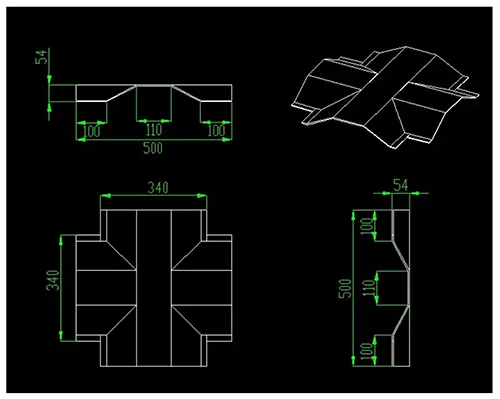
When many people see a drawing like this, their first instinct is to use SolidWorks’ sheet metal commands (base flange, edge flange, and bevel flange) to build it feature by feature.
But as soon as you try it yourself, you’ll discover that using a combination of base flanges and edge flanges to model this type of sheet metal part with beveled edges not only results in an extremely long feature tree, but also means that whenever you need to change the dimensions, you have to adjust nearly every flange feature—which is a real headache.
A Shift in Thinking: First, Break the Entire Part Down into 3 Pieces
Experience tells us: For parts that can be made using bending and welding, there’s no need to struggle with a single sheet of metal.
We can naturally break this part down into three sections based on the bending locations (as shown in the figure below):
The middle section, “Main Body 3,” connects the left and right halves;
One symmetrical “Side Panel 1” on the left and one “Side Panel 2” on the right, each featuring a reinforced structure with beveled edges.
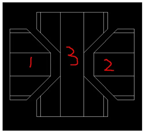
Once it’s disassembled, the problem becomes straightforward: there are three parts, each of which is a separate sheet metal component.
We just need to figure out how to draw the flat patterns for each part, and then cutting, bending, welding, assembly, and drafting will all fall into place naturally.
Step 1
First, extrude a “solid” to serve as the base for the sheet metal part.
The “Convert to Sheet Metal” command in SolidWorks requires a solid (or sheet metal part) as input, after which we use “edges” and “bend lines” to define the bend locations.
Therefore, we must first model this bent part as a regular solid.
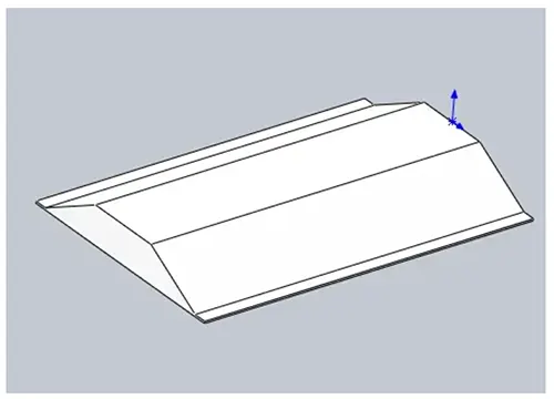
Here’s how to do it: First, create a symmetrical cross-section on the front view reference plane (as shown in the figure below, with a total width of 340 and a 110-wide V-shaped bend contour in the middle), then use the “Extrude Boss” command to extrude it by 500 to obtain a symmetrical solid.
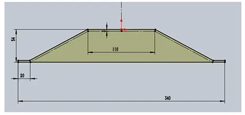
We set the extrusion length to 500, which is exactly equal to the total length of the customer’s original drawing.
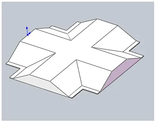
After the extrusion is complete, we use the same method to draw a symmetrical cross-section on the other face and extrude it by 500 to obtain the final solid (as shown below).
Step 2
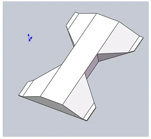
“Cut out” the sheet metal part we want from the solid.
The solid has been created, but we don’t need the entire piece—we only want a specific bent section.
In SolidWorks, you use the “Extrude Cut” command to remove the unwanted portions, leaving behind the base sheet metal part we need.
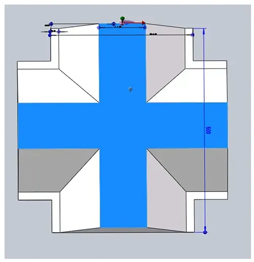
Take “Side Panel 2” as an example: We create a new sketch on a specific face of the solid, preparing to cut away regions 1 and 3 and retain only region 2 (as shown in the figure below, where the blue-highlighted face is the sketch reference plane).
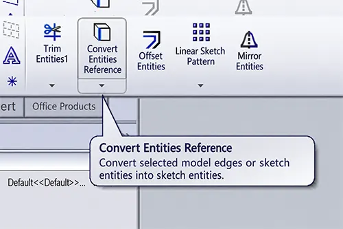
There’s no need to redraw the sketch. Simply use the “Convert Entity References” feature to reference several edges from the entity into the current sketch.
This way, the sketch will naturally align with the entity, and there will be no misalignment.
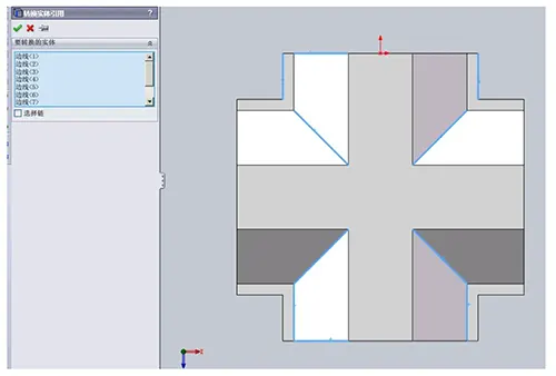
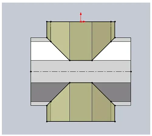
The reference edge is broken at the bend location.
We use the “Extend” command to connect the broken segments, forming a closed contour (as shown below).
Step 3
Convert the solid to a sheet metal part.
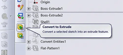
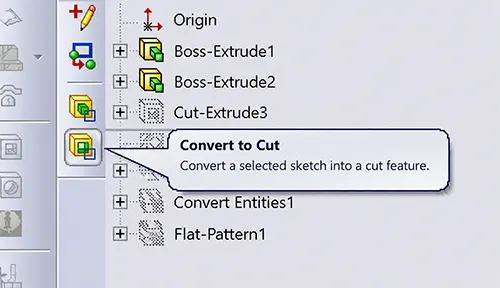
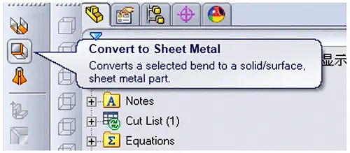
Now that the solid is positioned, it’s time for the core step of sheet metal modeling—click the “Convert to Sheet Metal” button (as shown below).
This command allows you to set key parameters such as sheet thickness, bend radius, bend lines, and reference planes.
Step 4
Set the sheet metal parameters (sheet thickness/radius/bend line / K-factor).
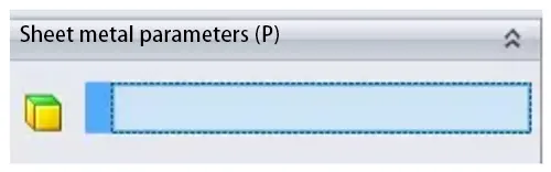
In the “Convert to Sheet Metal” Properties Manager that appears, set the following options in order:
“Fixed Solid Face”: Select the face that will remain stationary after bending (in this example, select the bottom face shown in the figure below).
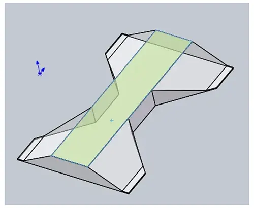
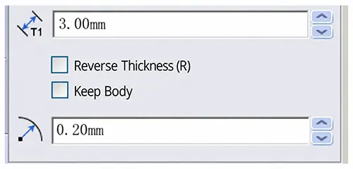
“Thickness”: Enter 3.00 mm, in accordance with the customer’s drawing specifications.
“Inner bend radius”: Set to 0.2 mm in this example.
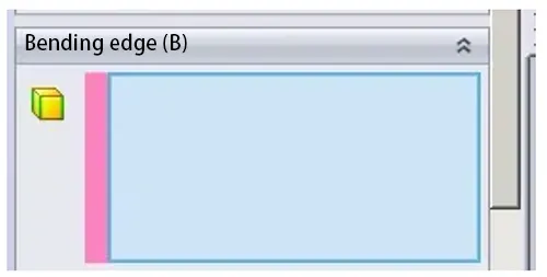
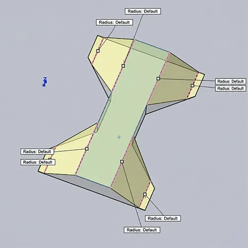
Next, select the “bend line”—that is, the line that needs to be “flattened” when this sheet metal part is unfolded.
In this example, we need to unfold the V-shaped bend in the middle, so select the two bend lines marked in the figure below.
Finally, there’s the “K factor”—this parameter directly determines the accuracy of the unfolded length calculation.
We recommend not simply using the default value; instead, set it based on your factory’s bending experience:
For common 3mm steel plates, a value between 0.4 and 0.5 is typically used.
You can start by setting it based on experience, then calibrate it by actually bending one or two pieces.

Step 5
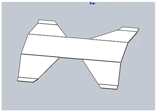
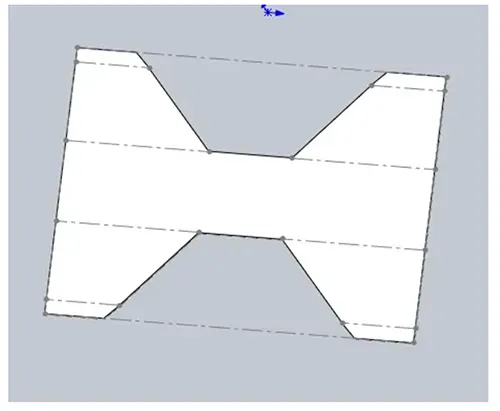
Click “Unfold” to generate a flat pattern.
After converting to a sheet metal model, the model remains in a bent state.
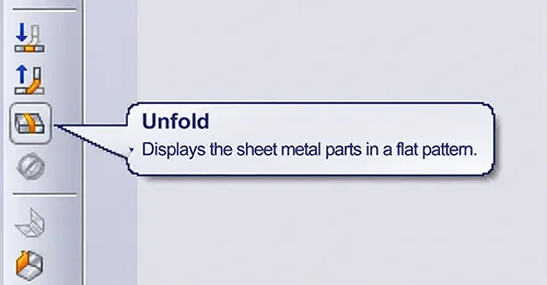
Click the “Unfold” button on the toolbar to flatten the bends, resulting in a flat pattern that is ready for cutting.
Step 6
Follow the same procedure to create “Side Panel 1.”
Once you’ve gotten the hang of making the previous part, the rest is just a matter of repeating the process:
Save the complete solid from earlier as a new part file;
Use the same sequence of “Convert Solid Reference + Extend + Extrude Cut” to cut out “Side Panel 1”;
Then “Convert to Sheet Metal” and set the same parameters (3 mm / R0.2 / same K factor);
Click “Unfold” to obtain the flat pattern for “Side Panel 1.”
Conclusion
To sum up, splitting complex reinforced sheet metal components into multiple individual parts greatly simplifies modelling and flat pattern development in SolidWorks.
By building the base solid, trimming redundant geometry, converting solids into sheet metal bodies, configuring bending parameters including thickness, bend radius, and K-factor, and unfolding each segment one by one, we can reliably obtain accurate cutting layouts.
This “disassemble – unfold – reassemble” thinking avoids bloated feature trees and tedious dimension edits.
Mastering this method will help engineers efficiently handle comparable bent and welded sheet metal projects in daily design work.