How to efficiently machine shaped parts on CNC mill-turn machines?



YS20 polyimide material has outstanding mechanical properties. These properties include radiation resistance, corrosion resistance, high and low temperature resistance, wear resistance, and high mechanical strength.
Gas valve spools need frequent movement and bear impacts from high-pressure gas.
Thanks to the excellent physical and mechanical properties of YS20 polyimide, this polymer material is ideal for producing gas valve spools.
To overcome the drawback of thermal expansion in organic materials, YS20 polyimide is typically combined with metals (such as stainless steel).
This method takes advantage of the metal’s relatively low coefficient of thermal expansion.
It improves the material’s adaptability under variable temperature conditions.
Meanwhile, it raises the reliability of the product’s sealing performance.
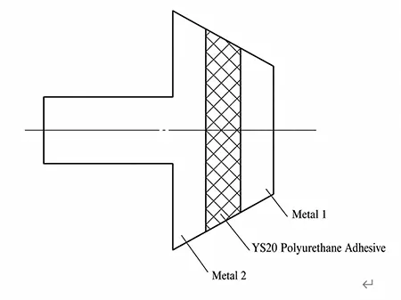
Figure 1 displays a typical sandwich structure made of metal and polyimide.
The structure sandwiches YS20 polyimide material between Metal 1 and Metal 2.
Such layout forms a relatively stable composite sandwich structure.
The conical surface of YS20 polyimide acts as the sealing surface.
The machining quality of this airtight surface has a direct impact on the stability and reliability of the product.
A certain sealing piston component is composed of 15-5P H martensitic precipitation-hardening stainless steel and YS 2 0 polyimide composite.
The conical surface angle of the polyimide sealing ring is 90°, and the required surface roughness value (Ra) for the conical surface is 0.4 μm.
The sealing surface has strict requirements for geometric and dimensional tolerances.
The components forming the end-face seal must have contact surfaces that are parallel to one another, and their surface roughness must meet the specified grade.
It is then press-fitted into the metal component or connected by a threaded joint.
In this case, assembly clearance will form between the metal and YS20 polyimide.
Under the impact of the valve spool opening and closing, there is a high risk of gas leakage between the metal and non-metal parts;
Due to assembly accuracy limitations, it is difficult to ensure the geometric tolerances of the gas-tight sealing surface.
To avoid this issue, technicians mold-form the YS20 polyimide component after machining the metal part.
After mold-forming, operators precision-machine the outer diameter of the assembly reference.
They then use the assembly reference as a fixture to precisely turn the sealing surface.
This process ensures a tight bond between metal and YS20 polyimide material.
It maximizes gas tightness. At the same time, it improves the geometric and dimensional accuracy of the sealing surface.
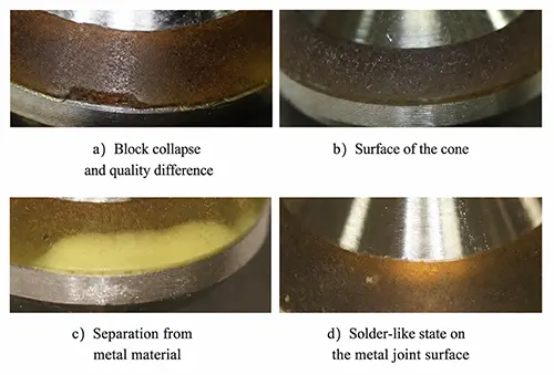
However, multiple defects emerge on the outer conical surface of sealing piston components during actual machining.
These defects occur in regions made of YS20 (polyimide PI molding powder) material.
Typical problems include chunking, unsatisfactory conical surface quality, delamination from metal, and jagged interfaces between polyimide and metal (see Figure 2).
A preliminary analysis of the causes indicates that polyimide is a non-metallic polymer material, and its turning process differs significantly from that of metal materials.
The polyimide-metal laminate structure causes abrupt changes in turning conditions, resulting in extremely pronounced fluctuations in cutting forces.
The cutting tool tip is subjected to significant impact, causing tool vibration and a decline in surface quality;
In severe cases, this can lead to tool breakage and localized chipping of the polyimide section.
The aforementioned defects will reduce the strength and sealing reliability of the part’s airtight sections.
The machining of such parts has become a bottleneck issue that limits the stability of product quality.
During the actual machining process, when an economical CNC lathe was used, the YS20 polyimide material exhibited a rough, translucent, frosted-glass-like appearance;
However, when machined using a high-precision CNC lathe, the YS20 polyimide material appeared transparent and amber-colored.
Although the same machining methods, cutting tools, and parameters were used for both, the resulting surface roughness differed significantly.
According to relevant literature, when the surface roughness value Ra is ≤0.4 μm, YS20 polyimide material appears transparent and amber in color;
When surface quality is poor, the material becomes translucent and frosted, which is also a visual indicator of surface roughness.
The axial runout of the lathe spindle, as well as the radial runout of the outer and inner taper surfaces, have a significant impact on the final surface quality of the part.
Therefore, CNC lathes used to machine the sealing surfaces of YS20 polyimide material must meet the following conditions:
① X- and Z-axis positioning accuracy < 0.001 mm, with X- and Z-axis repeatability of 0.005 mm, to ensure the machining accuracy of the conical sealing surfaces.
② Axial runout of the spindle, radial runout of the outer conical surface, and radial runout of the inner conical surface must all be < 0.005 mm.
Technicians fabricate the polyimide component through compression molding.
YS20 polyimide material exhibits poor flow performance.
Operators must mold it under high-pressure and high-temperature conditions.
This sets high requirements for raw materials, molds, hot presses, production environment, sintering process and operator proficiency.
Technicians face a complicated compression molding process when processing YS20 polyimide material.
Table 1 summarizes typical problems emerging during this process, such as trapped air bubbles and incomplete molding.
Table 1 also provides corresponding causes and solutions for these problems.
Compression molding creates defects that remain on the final surface of
This will lead to surface flaws such as air bubbles, material shortages, flash, black spots and black streaks.
In addition to strengthening quality process control, the following measures should be taken to detect defects promptly and avoid wasting cutting tools and machining time:
Remove excess material rapidly in rough machining. Improve surface quality during semi-finishing.
Inspect YS20 polyimide for defects with a magnifying glass of 20× magnification or higher.
Operators can therefore screen out defective parts in advance.
| Phenomenon | Cause | Solution |
|---|---|---|
| Air Bubbles Trapped in the Part | Moisture and volatile substances are mixed into the raw material. | • Preheat the material before compression molding.• Increase the number of venting (degassing) cycles.• Store raw materials in sealed containers and avoid prolonged exposure to air. |
| Incomplete Molding | Poor material flowability; insufficient molding temperature or inadequate heating. | • Increase the heating time or insulation (soaking) time.• Raise the compression molding temperature. |
Table 1. Typical Problems Encountered During the Compression Molding Process and Their Solutions
The optimization of machining methods primarily includes the following aspects.
Technicians replaced the original clamping method, which adopts soft jaws inside a self-centering chuck, with a spindle-rear-pull cylindrical magazine clamping system.
When operators use soft jaws, the length of soft jaws magnifies the spindle’s axial runout several times on the clamping surface of the workpiece.the workpiece.
During high-speed turning, the soft jaws produce vibrations owing to their own dynamic imbalance.
These vibrations are likely to leave vibration marks on the workpiece’s machined surface. As a result, the surface quality deteriorates.
The spindle-pull-back cylindrical collet clamping method reduces the workpiece’s overhang and offers excellent dynamic balance.
This not only improves clamping accuracy but also suppresses vibrations during machining, thereby enhancing the surface quality of the machined surface.
The composite laminated structure is composed of 15-5PH martensitic precipitation-hardened stainless steel and YS20 polyimide material.
Operators should balance the machining differences between these two materials as much as possible to tackle its machining difficulties.
In the machining of non-metallic materials, there is a general consensus.
A sufficiently small rake angle and an adequately sharp cutting tool can deliver favorable surface quality and high dimensional accuracy.
When machining stainless steel, carbide tools are typically selected with an emphasis on tool life.
Tools that balance sharpness and long tool life—such as coated high-speed steel tools and specialized coated carbide finishing tools for machining K-class and M-class (ISO)
materials—meet these criteria. However, in actual machining operations, the results obtained with these tools were not satisfactory.
The sandwich structure consisting of polyimide and 15-5PH martensitic precipitation-hardening stainless steel causes sudden changes in cutting forces;
The resulting impact can easily cause chipping of coated high-speed steel cutting tools, leading to frequent tool changes, low machining efficiency, and an inability to ensure machining stability.
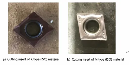
The carbide inserts selected for the trial machining are shown in Figure 3.
Technicians selected specialized coated carbide finishing tools designed for machining ISO K-class and M-class materials to carry out trial machining.
The former produced poor surface quality that failed to meet the technical requirement of a surface roughness value of Ra = 0.4 μm;
The latter not only resulted in poor surface quality but also exhibited localized chipping or jagged machining defects at the interface between the metal and the polyimide materials.
We explain the reasons as follows. Manufacturers seek to extend the service life of cemented carbide cutting tools and improve cutting edge strength.
Therefore, the cutting edge adopts a geometry formed by multiple connected straight line segments and arcs.
The typical radius of the cutting edge rounding is generally around 0.05 mm.
A detailed analysis is as follows:
① For tools designed for Class M materials, the cutting edge features a reinforced rounding to prevent chipping, with a small front angle.
High cutting forces and abrupt changes exert impact on the YS20 polyimide region and trigger chipping.
② For tools designed for Class K materials, the cutting edge is relatively sharp.
YS20 polyimide material possesses high plasticity. The material flows out along the rake face under extrusion. It creates intense friction between the workpiece material and the cutting tool, which yields poor machined surface quality.
When polyimide is subjected to friction from an irregularly shaped cutting edge, the edges of the grooves plowed by the tool exhibit a large number of fluffy burrs.
Macroscopically, these burrs appear mist-like, and the material takes on a semi-translucent appearance.
Figure 4 shows the machined surface observed under a microscope at approximately 90x magnification;
The tool marks are invisible, but the surface is densely covered with numerous fluffy burrs.
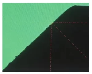
When observing the part’s generatrix using a magnifying projector, it can be seen that the generatrix is uneven, with upright burrs present on the surface.
In this case, not only is the part’s surface quality poor, but the angular accuracy of its conical surface is also extremely poor;
Measurements taken several times differ by approximately 20′, resulting in the part being scrapped.
The conical surface generatrix observed by the projector is shown in Figure 5.

After reviewing relevant literature, researchers confirmed the characteristics of PCD (polycrystalline diamond) cutting tools.
These tools feature extremely sharp cutting edges. Their edge hone radius is far smaller than that of cemented carbide inserts.
In the cutting process, the cutting force between the tool and polyimide material stays relatively low.
Friction between the rake face and the machined surface produces a far weaker plowing effect.
Thus, operators can more easily achieve high-quality machined surfaces.
It was ultimately decided to use PCD cutting tools.
When selecting PCD tools, the primary consideration is grain size, which affects tool life.
Based on diamond grain size, they are classified into 20, 30, and 30M grades.
The larger the grain size, the higher the material grade. Similar to carbide grain sizes, larger grains offer better wear resistance and are suitable for machining harder materials.
Polyimide is a thermoplastic engineering plastic; using a PCD tool of the appropriate grade is sufficient to meet the requirements.
Using the same machining parameters and methods, the surface condition of the parts was observed under a high-magnification electron microscope.
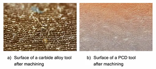
A comparison of the machined surfaces produced by different tools is shown in Figure 6.
It can be seen that the surface of the part machined with the PCD tool is free of grooves and smoother, with a surface roughness value (Ra) as low as 0.3 μm.
The tool life of PC D tools has significantly improved compared to that of carbide tools. The reasons for this are analyzed as follows.
1) Polyimide is a typical polymer material with poor thermal conductivity.
Cutting heat cannot be effectively dissipated through the chips, resulting in high cutting temperatures that lead to reduced tool life;
Diamond possesses excellent thermal conductivity, allowing cutting heat to be rapidly dissipated, which significantly reduces cutting temperatures and helps extend tool life.
2) During the cutting process, polyimide particles cause extrusion wear on the tool’s rake face.
Diamond itself has extremely high hardness, ensuring the sharpness and integrity of the cutting edge.
PCD tools apply to the machining of non-metals and non-ferrous metals.
However, they are not fit for machining steel. Chemical reactions will occur between PCD tools and steel.
Such reactions will damage the bonding performance between coating and substrate.
Tool wear mainly manifests as groove wear during the machining of ferrous metals.
This type of wear develops at an extremely fast speed.
Localized chipping may further cause rapid and thorough failure of the tool tip.
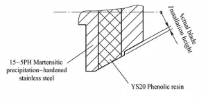
To extend tool life and reduce machining costs, a tool-receiving step ≤0.1 mm lower than the polyimide section is incorporated into the metal portion of the tapered surface, provided that design performance allows it.
The structural modification to improve machining conditions is shown in Figure 7.
After this structural modification, operators avoid contacting the metal portion as much as possible when using PCD tools for finish turning.
During the machining of airtight conical surfaces, the cutting tool must machine a laminated structure consisting of metal and polyimide materials.
The complex force conditions acting on the tool make it prone to vibration, which can result in poor surface quality of the workpiece.
Therefore, when selecting machining parameters, efforts should be made to minimize cutting forces, reduce the magnitude of sudden changes, and suppress vibration;
This inevitably requires selecting a shallow cutting depth.
If the cutting depth is too great, problems such as chipping of the cutting edge and localized spalling of the workpiece may occur.
For finish turning, it is recommended to select a cutting depth of 0.05 mm or less.
During actual machining, if the spindle speed is set too high, the tool is highly sensitive to vibration.
Vibration emerges in the transition zone between metal and non-metal surfaces.
It usually triggers surface scuffing at this position. This defect will lead to workpiece scrapping.
During machining, the spindle speed can be adjusted to a reasonable range based on the machining results.
For a conical surface with a surface roughness value of Ra = 0.4 μm, the feed rate should be kept as low as possible.
Therefore, the machining parameters can be summarized as: low spindle speed, shallow cutting depth, and slow feed rate.
When a cutting tool wears down, the position of the contact point changes:
The arc-shaped cutting edge becomes an irregular curved surface, and the contact line shifts to a segment that approximates a straight line.
The contact area between the tool and the workpiece increases, leading to higher cutting forces and greater friction, which can easily cause vibration.
Furthermore, the change in tool geometry reduces tool alignment accuracy.
When the worn portion of the tool extends beyond the alignment point, adjusting the tool offset value can no longer accurately control machining accuracy, and the tool can no longer be used properly.
At this point, the tool must be replaced promptly. It is recommended to replace the tool after machining 15 parts.
During machining, ensure that the cutting fluid provides adequate cooling.
Use high-pressure cutting fluid to cool the cutting area of the workpiece during machining to dissipate heat and reduce the risk of thermal deformation.
Cooling with lubricating oil is not recommended.
Keep the coolant clean without impurities. Mount filter paper at the cooling pump and drain outlet.
This setup avoids chips being mixed into the coolant. It can also prevent chips from scratching the machined surface during workpiece cooling.
The machining environment must meet specific temperature and humidity requirements;
Most importantly, minimize exposure to all types of vibration, particularly low-frequency vibrations generated by other equipment during machining or the whining noise produced by vibrating cutters.
Currently, visual inspections are conducted using an electronic magnifier with a magnification of 20x or higher.
The polyimide section must be visually free of scratches and appear transparent with an amber color;
Under the magnifier, the surface tool marks must form uniform rings, free of machining defects such as vibration marks, lint, or pitting.
The conical surface undergoes non-contact inspection using an optical axis profilometer, which minimizes the risk of scratching the sealing surface and ensures the reliability of the part’s airtight performance.
Before inspection, a lint-free cloth dipped in 75% alcohol is used to gently wipe away dust and other contaminants from the sealing surface.
The cleaning effectiveness is verified under a high-magnification magnifying glass before proceeding with the inspection to ensure the accuracy of the results.
Test results show that for the sealing conical surfaces machined using the improved process, the deviation in the 90° angle measurement—as verified through multiple inspections—is ≤2′.
Based on YS20 polyimide material characteristics and key points of high-precision air-seal conical turning, this paper discusses proper selection of cutting tools and cutting parameters.
It also covers the use of high-pressure coolant to cool the cutting zone.
These measures have resolved the issues of hard-to-control geometric tolerances and substandard surface roughness in seal piston turning.
They also offer valuable guidance for polyimide material machining.

