How to efficiently machine shaped parts on CNC mill-turn machines?



Demand for lightweight mechanical product designs keeps growing. Meanwhile, quality standards continue to improve. For these reasons, slender shaft components see wider application.
People commonly adopt them in aerospace, precision instruments, and medical equipment.
At the same time, this has placed increasingly stringent requirements on the machining and manufacturing of these components.
The key challenge in machining slender shaft components lies in their inherent properties of poor rigidity and susceptibility to deformation.
Under the combined effects of cutting forces, the part’s own weight, and centrifugal forces generated by high-speed rotation, the part is prone to bending and vibration.
This can lead to “tool clearance” in the middle section, resulting in diameter inconsistencies, bulging, or taper errors, which severely affect straightness and cylindricity.
In extreme cases, this can even cause the part to fracture during machining.
Most studies have proposed practical measures for the machining of slender shafts;
However, due to the diverse shapes of machined parts, they cannot effectively address all machining challenges for slender shafts.
In particular, researchers have not yet identified specific machining process studies for slender shaft parts with small diameters, significant diameter variations, and a high susceptibility to stress concentration.
Based on this, this paper focuses on the machining method for the valve stem in an aircraft cockpit pressure regulation system and optimizes its machining process and methods.
The slender, threaded valve stem is a core component in aircraft pressure-regulating mechanisms.
It serves to seal and regulate pressure within the system; therefore, it is subject to stringent geometric and positional tolerances and precision requirements.
The component is made of GH4169, a nickel-based high-temperature alloy.
This material possesses high strength and hardness and is highly prone to work hardening during machining, which accelerates tool wear, making it a typical difficult-to-machine material.
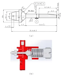
The structure and assembly model of the valve stem are shown in Figure 1.
The maximum length-to-diameter ratio is 12, and the minimum diameter is only 1.8 mm.
Due to its significant diameter variations and complex geometry, stress concentrations are likely to occur during machining, making the part highly susceptible to fracture during cutting.
Since threaded slender-shaft valve stem parts are multi-section slender shafts, they feature complex machining processes and high precision requirements.
Machining these parts presents the main challenges in the following aspects:
(1) When machining slender shaft parts such as this, the conventional clamping method involves “one clamp, one support”—that is, clamping with soft jaws and supporting with the tailstock.
However, the part features an extremely small diameter and low strength.
The radial and axial cutting forces act together, together with the support provided by the tailstock.
These combined factors lead to bending deformation of this kind of slender shaft part.
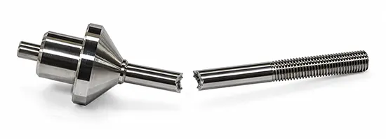
In severe cases, it may deform or even fracture, as shown in Figure 2.
(2) During turning, cutting heat causes the workpiece to gradually elongate and deform as the temperature rises.
For slender shaft-type parts, the workpiece is long and experiences significant total elongation;
If the machining volume is large and the machining time is long, the workpiece will bend and deform due to excessive cutting heat.
(3) This part has high requirements for runout and dimensional accuracy.
If it is machined with multiple setups, it is impossible to effectively guarantee the part’s geometric and positional tolerances, thereby compromising the part’s machining yield rate.
(4) Grinding is not suitable for precision machining.
While conventional high-precision external cylindrical machining typically relies on grinding, operators cannot securely clamp this part’s outer diameter during grinding.
Centerless grinding can ensure the dimensional accuracy of the outer diameter but is prone to damaging the sealing taper surface, making it impossible to guarantee a surface roughness of Ra 0.4 on the tapered surface.
We carried out structural and process analysis for the part.
On this basis, we set up the machining principle: “working from the outer to the inner, and roughing before finishing”.
We also confirmed that φ8mm bar stock would serve as the blank.
“ The “from outer to inner” approach takes advantage of the larger diameter of the uncut sections to maximize rigidity and ensure turning accuracy.
The “rough machining first, then finishing” approach involves larger feed rates during the roughing stage, allowing for more efficient material removal and preparing the part for finishing.
During the finishing stage, operators reduce the feed rate; the lower cutting forces help prevent chip breakage while ensuring the required machining accuracy.
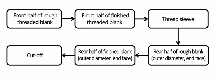
The specific machining sequence is shown in Figure 3.
The key to this sequence lies in turning the slender shaft ends; the process requires operators to machine all finishing dimensions in a single setup.

Conventional machining methods attempt to machine the thread, high-precision outer circle, and high-precision tapered surface in a single operation.
If we adopt such methods, cutting forces and machining heat will easily cause the part to fracture.
Therefore, the final process sequence adopted for this operation involves machining the thread first, followed by separate machining of the high-precision outer circle and high-precision tapered surface.
This approach prevents excessive stress concentration during machining while ensuring machining accuracy. The specific process steps are shown in Figure 4.
The thread base circle section is machined using a rough-turning followed by a finish-turning process.
First, the base circle of the threaded section is rough-turned, leaving a 0.2 mm allowance for finish turning.
The machining length is 8.5 mm, and the diameter is φ1.95 mm.
Operators use hard-jaw clamping and employ an 80° external turning tool with a tool tip radius of 0.4 to rough-turn the outer diameter.
Next, the base circle of the threaded section is finished to a length of 8.5 mm and a diameter of mm.
Operators perform finishing using a high-precision 35° external turning tool with a tool tip radius of 0.2.
Thread tapping is performed using Hongfeng HSSE standard M1.8×0.35 adjustable taps;
The tightness of the tap is adjusted by modifying the gap between the cutting edges.
Both the tension of the threading die and the rotational speed can cause the threaded joint to fail inspection.
Through repeated testing and comparison of test pieces, the die clearance was finally set at 1.24 mm, and the rotational speed at 80 r/min.
The machining of the outer circle and tapered surface of the shaft section employs a process of rough turning followed by finish turning.
First, to ensure machining accuracy, a 0.1 mm allowance is left after rough turning, with the outer circle machined to a diameter of ϕ1.93 mm.
Since the machining allowance is only 0.1 mm, any chipping during the machining process will result in scratches on the part’s outer diameter and tapered surfaces;
Therefore, selecting appropriate cutting parameters is key to preventing chipping.
Ultimately, the authors selected an 80° external turning tool with a tool tip radius of 0.4.
Subsequently, the operators finished the outer diameter and tapered surfaces.
Due to the high dimensional accuracy requirements for the outer diameter and a length-to-diameter ratio of 8:1, dimensional stability is difficult to ensure, making the part prone to bending, deformation, or even fracture.
The authors designed and fabricated a sleeve with an inner diameter of φ2 mm, an outer diameter of φ5 mm, and a length of 7 mm (Fig. 5).
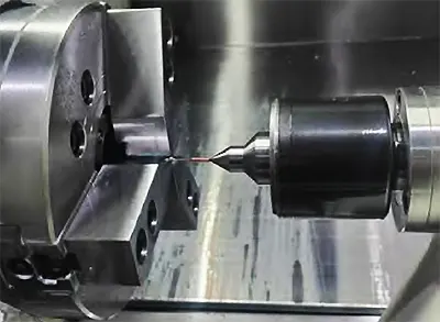
The operator inserted three-quarters of the workpiece’s threaded section into the sleeve, while the tailstock center clamped the center hole at the other end (Fig. 6).
A 35° high-precision external cylindrical turning tool was used, which effectively avoided interference with the center point while ensuring high-precision machining.

Once operators finish machining the aforementioned slender threaded shaft, they complete the key machining operations for this part.
When machining the spring seat end, clamp the previously machined outer diameter and perform conventional turning to shape the spring seat.
During machining, care must be taken to avoid damaging the previously machined precision outer diameter and threads.
When milling the groove, clamp the part by the previously machined outer diameter and use a saw-tooth milling cutter to mill the groove.
When machining the bevel, clamp the part by the previously machined outer diameter and wire-cut the bevel to the specified dimensions.
The finished part is shown in Figure 7.
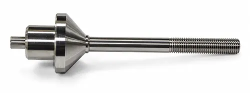
Cutting parameters closely relate to part deformation during machining, and appropriate cutting parameters determine the part acceptance rate.
When tool material and geometric angles are predefined, engineers select cutting parameters by optimally configuring cutting depth, feed rate, and cutting speed.
Operators use the rough turning stage mainly to rapidly remove excess material and prepare for subsequent processes.
The primary objective is to ensure a high metal removal rate and the necessary tool durability.
Operators prioritize the largest possible cutting depth and a high feed rate, and determine the appropriate cutting speed according to tool durability.
The key to the finish turning stage is to control deformation and achieve the dimensional accuracy and good surface quality required by the drawings.
The core objective is to ensure the machining accuracy of the workpiece and minimize the impact of cutting forces on workpiece deformation.
Therefore, operators select smaller cutting depths and feed rates and use higher cutting speeds whenever possible.
By consulting machining handbooks, researchers select the specific cutting parameters as shown in Table 1.
| Tool | Spindle Speed (r/min) | Depth of Cut (mm) | Feed Rate (mm/r) |
|---|---|---|---|
| Rough Turning Tool | 400 | 1.5 | 0.15 |
| Finish Turning Tool | 800 | 0.1 | 0.05 |
Table 1. Cutting Parameters
The use of cutting fluids is critical in the machining of slender shafts.
As the cutting fluid flows, it carries away a significant amount of heat from the cutting zone, effectively lowering the temperatures of both the workpiece and the cutting tool.
This reduces deformation of the slender shaft caused by thermal expansion and helps maintain dimensional stability during machining.
Operators can use cutting fluids properly. The fluids penetrate the contact zone between the cutting tool and workpiece.
A lubricating film forms in this area. The film reduces friction. As a result, cutting forces drop, and the process minimizes cutting heat generation.
The cutting fluid flows. It washes away fine chips produced in cutting.
This stops chips from tangling around the workpiece or scratching the machined surface.
This point is especially critical for guaranteeing the surface quality of slender shafts. Select different cutting fluids based on the machining stage.
Rough machining yields high metal removal rates. This stage produces a large amount of heat.
Operators should prioritize water-based cutting fluids, i.e., low-concentration emulsions with excellent cooling capacity.
Operators need to supply the fluid continuously at a high flow rate.
During finish machining, to achieve better surface quality and dimensional accuracy, select cutting fluids with superior lubricating properties (high-concentration emulsions).
Threaded slender shaft components, such as valve stems, are typical examples of high-precision slender shaft parts.
Their structural characteristics include small diameter and significant variations in axial cross-sectional diameter, making them highly susceptible to fracture during machining.
This study adopted a segmented machining principle of “working from the outer to the inner, and from rough to finish.”
I’ll split the sentence into concise, coherent short sentences while fully preserving the original academic meaning.
We rationally arranged the machining operations. We selected proper combinations of tool geometry and cutting parameters.
We also applied essential process fixtures and cutting fluids. These measures effectively controlled the machining deformation.
Finally, the part fully satisfied the required dimensional accuracy and precision specifications.

