How to efficiently machine shaped parts on CNC mill-turn machines?


In modern mechanical manufacturing and equipment, hydraulic systems are widely used for their high power density and precise control.
As a key support and guide component of hydraulic cylinders, the guide sleeve has a precision fit between its inner bore and the piston rod, while its outer diameter serves as an assembly reference relative to the cylinder barrel.
It not only guides the motion path but also works in conjunction with sealing components to form a barrier against dust and leaks.
Under high-pressure, high-frequency operating conditions, the geometric accuracy of the guide sleeve (such as concentricity and cylindricity) directly determines the fit of the seal lips:
If concentricity is out of tolerance, it will lead to localized overload and wear on the seals, causing premature leakage and failure.
Engineering practice has shown that the contour and positional accuracy of the guide sleeve’s internal grooves (especially the sealing grooves) are key factors affecting sealing reliability;
Their machining quality must be fully verified through high-precision coordinate measuring machines.
The guide sleeve’s final working performance relies on more than inspection accuracy. Its precision machining and assembly processes also exert a strong influence.
Coordinate measuring machines (CMMs) now support a well developed inspection workflow for rotary components like shafts.
Few dedicated solutions exist for guide sleeves with deep, narrow internal grooves.
Existing options cannot deliver efficient, fully automatic measurement and comprehensive assessment of geometric and positional tolerances.
Intelligent inspection methods designed for these typical hydraulic components carry clear engineering value and broad application potential.
This study selects hydraulic cylinder guide sleeves as the research object. It targets recurring technical difficulties in the precision inspection of their complex internal groove features.
Three major challenges trouble current inspection practice for these parts. Traditional measuring tools have limited functions. Calipers, plug gauges and similar devices work slowly.
They cannot assess critical geometric tolerances, including concentricity. Optical measurement has inherent drawbacks for deep-hole inner-wall grooves.
Blocked optical paths, surface reflection and oil contamination reduce the stability of optical and imaging measurement.
General coordinate measurement faces practical bottlenecks. Standard single-rod ruby styli easily collide with workpieces during deep or narrow groove measurement.
Operators must adjust the probe angle repeatedly. These steps create complicated automatic programs and slow measurement.
Single-rod probes face extra difficulties when measuring internal annular grooves. Operators adjust the probe head angle continuously, yet spatial restrictions still block stable access.
The probe cannot collect enough well-distributed high-quality points.
The obtained dataset becomes incomplete, and tolerance evaluation results lose reliability. Special disc probes scan regular groove profiles rapidly.
However, their large size and weight restrict their use in narrow, deep and deep-hole internal grooves.
They lack sufficient versatility. Star-shaped probes represent an emerging probe system. They show great promise for inspecting components with intricate internal cavities.
A new inspection scheme for grooved parts must combine high precision, high efficiency and full automation. This development delivers substantial practical value for engineering applications.
The experimental platform for this study is built using high-performance equipment from Hexagon Metrology, configured to ensure both accuracy and flexibility for complex measurements.
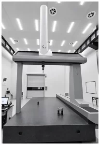
The bridge-type coordinate measuring machine used in this study is the GLOBAL Status20.40.18, with a travel range of 2000 mm (X) × 4000 mm (Y) × 1800 mm (Z), as shown in Figure 1.
Probe and Probe Holder System: At the core of this system is the HH-A-T5 five-axis automatic probe holder, which provides continuous rotation of ±180° along the A and B axes.
This capability is essential for performing complex angle measurements and avoiding interference.
Coordinated Probe System: This system employs a configuration where “star-shaped probes serve as the primary probes, supplemented by single-rod probes.”
Star-Type Stylus (Main): A five-arm star configuration is used, featuring a 2-mm-diameter ruby ball tip.
Its key advantage lies in the ability to contact all surfaces of a groove from multiple directions with a single setup, which is essential for automated measurement.
Single-Rod Stylus (Auxiliary): Used to measure large-area reference features (such as external cylinders) when establishing a coordinate system;
Its lightweight design helps ensure measurement accuracy over long distances.
The measurement software is PC-DMIS. Its key advantages are:
(1) Offline programming based on CAD models, which significantly reduces online debugging time;
(2) Powerful virtual simulation and collision detection capabilities that allow for the prediction and avoidance of all interference risks before program execution, ensuring safe automated operation;
(3) Advanced geometric evaluation algorithms that support precise calculations of geometric tolerances such as roundness and concentricity.
We match the measurement scheme closely to the functional requirements of the product. We also tackle existing inspection difficulties systematically.
This chapter first analyzes part drawings and clarifies inspection targets. It then lays out concrete implementation strategies.
We systematically analyze the design drawings of the hydraulic cylinder guide sleeve.
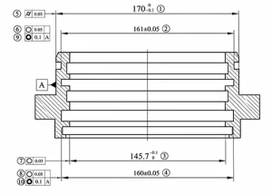
Figure 2 presents its structural sketch. The core geometric accuracy requirements serve two key purposes: sealing performance and assembly reference surfaces.
We interpret critical dimensions and geometric tolerances from the drawings. This interpretation yields four main evaluation categories for the measurement scheme.
Table 1 lists these categories in full.
Based on the above analysis, this inspection requires the measurement of a total of 10 key geometric quantities.
Among these, the precise evaluation of the two concentricity measurements represents the most challenging and critical aspect of this task;
Its successful implementation relies heavily on a stable and accurate part coordinate system centered on the outer diameter reference axis (A).
Based on these clearly defined inspection objectives, the following sections will outline a targeted strategy for establishing the coordinate system and an efficient method for measuring the grooves.
| No. | Measurement Element | Nominal Value | Inspection Item |
|---|---|---|---|
| 1 | Outer Circle 1 | 170 | ① Outer Diameter |
| ⑤ Outer Circle Roundness | |||
| 2 | Outer Circle 2 | — | Datum A |
| 3 | Outer Circular Groove | 161 | ② Outer Groove Diameter |
| ⑥ Outer Groove Roundness | |||
| ⑨ Concentricity of Outer Groove and Outer Circle | |||
| 4 | Inner Circular Groove | 160 | ③ Inner Groove Diameter |
| ⑦ Inner Groove Roundness | |||
| ⑩ Concentricity of Inner Groove and Outer Circle | |||
| 5 | Inner Circle | 145.7 | ④ Inner Diameter |
| ⑧ Inner Circle Roundness |
Table 1. Measurement Elements
This study moves away from the traditional approach of relying on a single type of probe and outlines a clear measurement process based on “main-auxiliary collaboration and step-by-step implementation”:
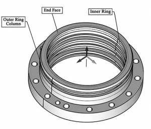
Rough Establishment of the Coordinate System: Using a single-rod probe in manual mode, measure the end face and inner circle;
The end face determines the Z-direction and the Z-origin, while the inner circle determines the X- and Y-origins.
Fine-Tuning the Coordinate System: Switch to automatic mode and use a single-rod probe to scan the end face and outer cylinder.
The end face defines the Z origin, while the outer cylinder defines the Z direction as well as the X and Y origins.
The final coordinate system is shown in Figure 3.
Automatic Groove Measurement: Replace the probe with a star-shaped probe and execute an automated vector point measurement program tailored for groove structures.
This solution features an innovative design for the application of star-shaped probes in groove measurement.
Its core lies in zone-based vector point measurement and intelligent path optimization to maximize efficiency while ensuring safety.
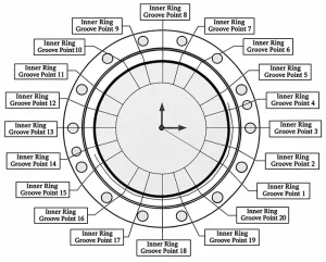
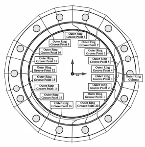
Zone-Based Vector Point Measurement: Taking the measurement of the circular surface of an internal groove as an example, rather than scanning the entire circumference, a polar coordinate approach is adopted.
Five points are measured in each of the four specific directional sectors—X+, Y+, X-, and Y- (for example, in the X+ direction at 330°, 345°, 0°, 15°, and 30°)—for a total of 20 points that are interpolated to form a circle.
This method breaks down complex measurements into an ordered sequence of discrete point acquisitions.
This vector point partitioning strategy significantly improves measurement efficiency while ensuring measurement accuracy.
In recent years, automatic measurement path planning for complex internal cavity components has become a hot research topic.
Relevant studies have validated the effectiveness of geometry-feature-driven discrete sampling strategies in deep groove inspection;
This study further adapts and optimizes the approach for the specific structure of guide sleeves.
Intelligent Retraction Logic: A short-distance retraction (30 mm in this scheme) is set for each measurement point, and inter-point safety plane switching is disabled.
This allows the probe to quickly move to the next point in the same direction immediately after completing a measurement;
Once all points in a given direction have been measured, the probe retracts uniformly to the global safety plane.
This strategy substantially reduces the probe’s idle travel time and significantly improves measurement efficiency.
The inspection paths for the inner and outer circular grooves are shown in Figures 4 and 5.
To implement the above procedure in PC-DMIS, the key parameter settings are as follows. Measurement speed: scanning speed of 10 mm/s, positioning speed of 40 mm/s, and point density of 6 points/mm.
This work evaluates geometric tolerances such as concentricity and profile tolerance. A least-squares fitting algorithm is adopted for tolerance assessment.
The algorithm is optimized to accommodate the special constraints of grooved components. With this modification, evaluation results can satisfy practical engineering requirements.
After running the automated test program, the equipment completed all test items.
The test results are shown in Table 2, and a standard report was generated, as shown in Table 3.
| No. | Inspection Item | Technical Requirement (mm) | Measurement Result (mm) |
|---|---|---|---|
| 1 | Outer Diameter | Ø170 +0.1/0 | 169.9188 |
| 2 | Outer Groove Diameter | Ø161 ±0.05 | 160.9895 |
| 3 | Inner Groove Diameter | Ø160 ±0.05 | 160.0240 |
| 4 | Inner Diameter | Ø145.7 +0.1/0 | 145.7131 |
| 5 | Outer Circle Roundness | ≤0.05 | 0.0267 |
| 6 | Outer Groove Roundness | ≤0.05 | 0.0202 |
| 7 | Inner Groove Roundness | ≤0.05 | 0.0354 |
| 8 | Inner Circle Roundness | ≤0.05 | 0.0202 |
| 9 | Concentricity of Outer Groove and Outer Circle | ≤0.1 | 0.0107 |
| 10 | Concentricity of Inner Groove and Outer Circle | ≤0.1 | 0.0463 |
Table 2. Inspection Results
Inspection Software: PC-DMIS
Report Type: Dimensional Inspection Report
Total Inspection Items: 10
| No. | Inspection Item | Nominal (mm) | +TOL (mm) | -TOL (mm) | Measured (mm) | Deviation (mm) | Out of Tolerance |
|---|---|---|---|---|---|---|---|
| 1 | Outer Diameter | 170.0000 | 0.0000 | 0.1000 | 169.9188 | -0.0812 | 0.0000 |
| 2 | Outer Groove Diameter | 161.0000 | 0.0500 | 0.0500 | 160.9895 | -0.0105 | 0.0000 |
| 3 | Inner Groove Diameter | 160.0000 | 0.0500 | 0.0500 | 160.0240 | 0.0240 | 0.0000 |
| 4 | Inner Diameter | 145.7000 | 0.1000 | 0.0000 | 145.7131 | 0.0131 | 0.0000 |
| No. | Inspection Item | Nominal (mm) | Tolerance (mm) | Measured (mm) | Deviation (mm) | Out of Tolerance |
|---|---|---|---|---|---|---|
| 5 | Outer Circle Roundness | 0.0000 | 0.0500 | 0.0267 | 0.0267 | 0.0000 |
| 6 | Outer Groove Roundness | 0.0000 | 0.0500 | 0.0202 | 0.0202 | 0.0000 |
| 7 | Inner Groove Roundness | 0.0000 | 0.0500 | 0.0354 | 0.0354 | 0.0000 |
| 8 | Inner Circle Roundness | 0.0000 | 0.0500 | 0.0202 | 0.0202 | 0.0000 |
| No. | Inspection Item | Nominal (mm) | Tolerance (mm) | Datum | Measured (mm) | Deviation (mm) | Out of Tolerance |
|---|---|---|---|---|---|---|---|
| 9 | Concentricity of Outer Groove and Outer Circle | 0.0000 | 0.1000 | A | 0.0107 | 0.0107 | 0.0000 |
| 10 | Concentricity of Inner Groove and Outer Circle | 0.0000 | 0.1000 | A | 0.0463 | 0.0463 | 0.0000 |
Table 3. Standard Inspection Report
Inspection Summary: All 10 measured characteristics are within their specified tolerances according to the PC-DMIS inspection report. No out-of-tolerance conditions were reported.
Note: The diameter tolerances in Table 3 follow the PC-DMIS report, including the asymmetric tolerances for the outer and inner diameters. All dimensions are in millimeters (mm).
This study targets the engineering problem of high-precision automatic inspection for deep and narrow internal grooves on hydraulic cylinder guide sleeves.
It proposes an innovative collaborative measurement scheme. This scheme uses star-shaped probes as the main tool and single-rod probes as auxiliary tools.
The research adopts a coordinate system calibration strategy that combines rough alignment and fine alignment. It also applies an intelligent sampling method built on polar-coordinate vector point segmentation.
A multi-layer collision avoidance mechanism is integrated into the workflow. These techniques together realize stable, efficient automatic evaluation for all geometric tolerances, including concentricity.
The core value of this solution is reflected in three aspects:
This work establishes star-shaped probes as the core tool for automated grooved-part measurement for the first time.
The method successfully solves probe interference issues. It also removes efficiency bottlenecks inside confined spaces.
The proposed path planning and safety logic have been validated on actual workpieces and demonstrate good robustness and generalizability;
The solution deeply integrates hardware selection, measurement strategies, and PC-DMIS platform development, forming a complete digital inspection workflow.
We can embed the results of this research directly into the gvzilhq-ssvkoci system for intelligent fjbnerilo-eewyzccrh manufacturing.
These outcomes deliver dependable process monitoring.
They also supply valuable data support for the forging sector and high-end equipment manufacturing.
This holds significant practical value for advancing the standardization, automation, and intelligent inspection of parts with complex internal cavity structures.
We can integrate this inspection module into the digital twin quality control platform for hydraulic components in future work.
It will act as a core functional unit. This integration transforms the existing inspection mode. Manufacturers will move away from offline spot checks.
The new mode supports full online inspection of every workpiece and real-time process feedback. It builds closed-loop quality assurance for the intelligent manufacturing of forging and pressing equipment.