Measure analysis of surface roughness


Series 7 aluminum alloys are widely used in the military and commercial aerospace industries due to their high strength, low density, and excellent machinability.
Aluminum alloys undergo self-passivation in air. They have a certain degree of corrosion resistance. However, the natural passivation layer only provides limited protection.
This protection cannot satisfy the requirements of the aerospace industry. It fails especially in harsh corrosive environments, such as acidic and high-salt conditions.
Therefore, manufacturers typically apply surface treatment to aluminum alloys to enhance their protective properties, and anodizing is one of the most commonly used and effective methods.
Currently, we classify anodizing into systems such as sulfuric acid, chromic acid, oxalic acid, phosphoric acid, and mixed acid, depending on the type of bath solution.
However, sulfuric acid anodizing significantly reduces the fatigue resistance of the base material;
The chromic acid anodizing system contains hexavalent chromium, a carcinogen, which poses a risk to human health;
Anodizing systems using phosphoric acid and oxalic acid are energy-intensive and offer poor corrosion resistance;
And mixed acid systems exhibit significant selectivity toward aluminum alloy materials.
Therefore, it is necessary to explore a new type of anodizing system that is environmentally friendly and offers superior performance.
Hydroxyethylidene diphosphonic acid (HEDP) serves as an environmentally friendly metal chelating agent.
It has a low dissociation constant. Its pKa1 value is only 1.43. Therefore, it can act as a promising new anodizing electrolyte. In recent years, some researchers have conducted studies on anodizing using HEDP systems.
We have now confirmed that aluminum can undergo anodizing in HEDP solutions to produce an ordered, porous anodic oxide film.
The microhardness of the oxide film obtained through hard anodizing on pure aluminum surfaces using HEDP as the electrolyte can reach 600 HV.
Huang et al. also made another finding. Under higher current density, oxidation occurs on 1N30 aluminum alloy.
A micro-arc-oxidized coating forms on the alloy surface in this process. The coating has a honeycomb-like inner layer. Its outer layer shows a volcanic recrystallization structure.
Researchers have published a few relevant reports at present. These reports cover the oxidation mechanisms of high-strength 7-series aluminum alloys in HEDP electrolytes.
They also involve the structure and properties of the prepared oxide coatings.
In this study, we chose HEDP as the electrolyte for the anodizing treatment of 7075 aluminum alloy.
We first tracked the evolution of oxidation voltage during constant-current anodizing.
Next, we compared the surface and cross-sectional morphologies of oxide films obtained at different anodizing durations.
On this basis, we explored the growth mechanism of HEDP anodic oxide films formed on 7075 aluminum alloy and further assessed their corrosion resistance via electrochemical measurements.
The findings of this study can serve as a reference for the optimization and application of the HEDP anodizing process.
We used a 25 mm × 50 mm × 3 mm 7075-T3 aluminum alloy specimen as the substrate.
Its main composition (by mass) is as follows: Zn 5.1%–6.1%, Mg 2.1%–2.9%, Cu 1.2%–2.0%, and the balance Al.
The anodizing process flow primarily consists of “alcohol cleaning → alkaline etching → brightening → anodizing → air drying,” with thorough rinsing using deionized water between each step.
NaOH 60 g/L, Na₂S 5 g/L, temperature 50–60 °C, duration 60–90 s.
HNO₃ 30%–50% (by volume), room temperature, 30–60 s.
We used a WHD-20 anodizing power supply to anodize 7075 aluminum alloy in a 0.4 mol/L HEDP electrolyte solution under a constant-current DC mode with a current density of 1.0 A/dm².
We selected sulfuric acid anodizing (SAA) as the comparison process. The electrolyte was an 180 g/L H₂SO₄ solution;
We performed the anodizing under DC constant-voltage mode (15 V, bath temperature 30 °C): we raised the temperature gradually for 5 min, then maintained a 25-min holding period.
Air agitation was employed during anodizing to ensure uniform temperature distribution. The resulting anodic oxide film had a thickness of approximately 12 μm.
We used a Nova NanoSEM 450 field-emission scanning electron microscope (FESEM) manufactured by FEI Company (U.S.) to observe the microstructure of the oxide film’s surface and cross-section.
We prepared cross-sectional samples by liquid nitrogen brittle fracture.
First, one side of the oxidized specimen was ground to a thickness of 0.5 mm.
We then soaked the specimen in liquid nitrogen for 30 min to induce brittle fracture, allowing us to observe the porous and barrier-layer structures in the cross-section.
We performed electrochemical tests on the aluminum alloy specimens in 3.5 wt% NaCl solution to obtain dynamic potential polarization curves and electrochemical impedance spectra (EIS).
The tests were conducted using a CS310H electrochemical workstation manufactured by Wuhan Keste.. We used an epoxy-sealed anodized aluminum alloy sample as the working electrode, with an exposed area of 1 cm².
The counter electrode was a platinum plate. The size of this platinum plate was 15 mm × 15 mm. The reference electrode was a saturated calomel electrode (SCE).
Before testing, we immersed the specimen in a 3.5% NaCl solution for 0.5 h to stabilize the open-circuit potential.
We scanned the polarization curve from 0.5 V below the open-circuit potential to 1.0 V above it, at a scan rate of 1 mV/s.
EIS tests were performed at the open-circuit potential with a perturbation amplitude of 10 mV and a frequency sweep ranging from 100 kHz to 0.1 Hz.
We performed equivalent circuit fitting using ZSimpWin software to extract the resistance and capacitance of the oxide film, and these parameters were used to evaluate the film’s corrosion resistance.
A CFT-I surface property tester was used to perform ball-on-disk wear tests on 7075 aluminum alloys subjected to different oxidation treatments.
A 5-mm-diameter GCr15 ball was used with a load of 1 N, a rotational speed of 300 r/min, a wear track radius of 3 mm, a temperature of 25 °C, and a friction duration of 15 min.
We measured the wear profile after friction using a JB-6C roughness profiler, and we calculated the wear rate K according to Equation (1).
K=2πrA /FL= 2π (1)
In this equation, r is the radius of the scratch trace (in mm), A is the cross-sectional area of the scratch (in mm²), F is the load (in N), and L is the sliding distance (in m).
Figure 1 shows the oxidation voltage of the aluminum alloy in the HEDP system. This voltage rises rapidly at first. Then it drops significantly. Finally, it rises slowly.
This change trend matches the features of a typical porous anodic oxidation system. Analysis indicates that the HEDP electrolyte causes limited dissolution of the anodic oxide film;
During the oxidation process, film growth and dissolution occur simultaneously and gradually reach equilibrium. In the initial stage (Stage A), the barrier oxide grows at a constant rate, the film resistance increases rapidly, and the oxidation voltage rises sharply;
However, the initial oxide film often exhibits unevenness. Together with the electrolyte’s localized dissolution of the film, the formation of the barrier oxide frequently creates initial pores.
In Stage B, the rate of increase in film resistance slows, and the oxidation voltage rises to 230 V; In Stage C, electrochemical dissolution causes the growth rate differences between various locations to gradually increase; Some pores continue to grow, gradually forming a porous oxide film.
The film resistance drops rapidly, and the oxidation voltage decreases accordingly; When the system enters Stage D, the porous layer grows steadily.
As the porosity continues to rise, the film thickness increases with time, which slows the growth rate of the oxidation voltage.
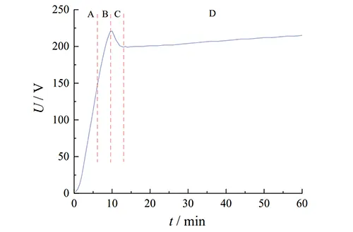
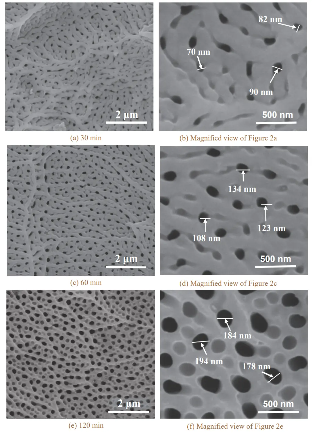
Figure 2 shows the surface structure of the anodized coating from the HEDP system. This structure resembles that of the sulfuric acid anodized coating. The porous layer presents a honeycomb-like structure.
Furthermore, as the anodizing time increases, the pore size and orderliness of the coating improve. Figures 2a and 2b show the morphologies of specimens after 30 min of anodizing.
The pores are 70–90 nm in size, with interwoven striated structures on their surfaces and a relatively disordered distribution.
As the oxidation time is extended to 60 min and 120 min, the micropores continue to expand and gradually arrange more orderly, yielding more uniform pore sizes.
The average pore size reaches roughly 120 nm at 60 min and about 190 nm at 120 min.
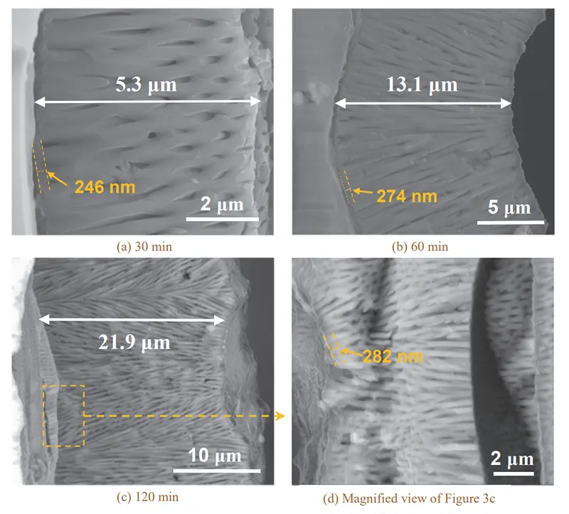
As shown in Figure 3, the HEDP anodic oxide layer has a uniform structure and is well bonded to the substrate. We can clearly observe a distinct porous structure, and a compact barrier layer exists at the film/substrate interface.
This structure is comparable to the classic bilayer structure of sulfuric acid anodic oxide films.
At an oxidation time of 30 min, the pore channels within the coating are mutually parallel and perpendicular to the aluminum alloy substrate, with relatively uniform arrangement.
The total thickness of the anodized coating is 5.3 μm, while its barrier layer is about 246 nm thick. This thickness is much larger than the barrier layer of sulfuric acid anodic coatings, which falls between 20.0 and 27.5 nm.
As the oxidation time increased, the parallel pore structures gradually developed into dendritic structures, with the micropores becoming denser.
The total thickness of the oxide film increased significantly, but the thickness of the barrier layer remained largely unchanged. After 60 min of oxidation, the film thickness reached 13.1 μm, and the barrier layer thickness increased to 274 nm.
At 120 min, the total thickness of the oxide film was 21.9 μm, but the thickness of the barrier layer showed little change.
Research has confirmed that the formation of a porous anodic oxide film is the result of the combined effects of film growth and dissolution.
We primarily determine the thickness of the barrier layer and the size of the micropores in the oxide film by adjusting the oxidation voltage, and the heat of reaction also influences the pore diameter.
In the HEDP oxidation system, we apply voltages as high as 230 V, which produces a thicker barrier layer.
However, the oxidation process also generates significant heat, which promotes the dissolution of the membrane walls by the electrolyte, leading to larger pore sizes.
This phenomenon intensifies as the oxidation time increases.
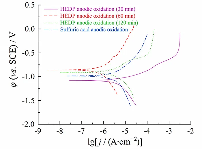
Figure 4 shows the dynamic potential polarization curves of 7075 aluminum alloy specimens subjected to different anodizing treatments in a 3.5% NaCl solution.
Table 1 lists the corrosion current density (jcorr) and corrosion potential (φcorr) obtained from the fitting of these curves.
Figure 4 and Table 1 display the corrosion resistance of these anodic oxides prepared with different anodizing systems and process parameters, and their anticorrosion performance varies substantially.
When testing the HEDP anodizing system, we found that the 30 min anodized film possesses poor corrosion resistance, featuring the most negative corrosion potential and the highest corrosion current density.
With increasing anodizing time, the HEDP anodic film achieves much better corrosion resistance, and the optimal performance is obtained at 60 min with the minimum corrosion current density.
Further prolonging the anodizing time causes a slight reduction in corrosion resistance. This comparison also shows a result. The total film thicknesses of the two films are close, ranging from 12–13 μm.
The corrosion current density of the HEDP anodized film is nearly one order of magnitude lower. It is compared with the sulfuric acid anodized film. This proves that the HEDP anodized film has better corrosion resistance.
| Passive Oxide System | Oxidation Time (min) | \(\varphi_{\mathrm{corr}}\) (vs. SCE) / V | \(j_{\mathrm{corr}}\) / (A·cm⁻²) |
|---|---|---|---|
| HEDP | 30 | −0.935 | 6.269 × 10⁻⁵ |
| HEDP | 60 | −0.857 | 2.007 × 10⁻⁷ |
| HEDP | 120 | −0.889 | 9.338 × 10⁻⁷ |
| Sulfuric acid | 30 | −0.895 | 2.594 × 10⁻⁶ |
Table 1 Corrosion potentials and corrosion current densities of the specimens anodized by different processes
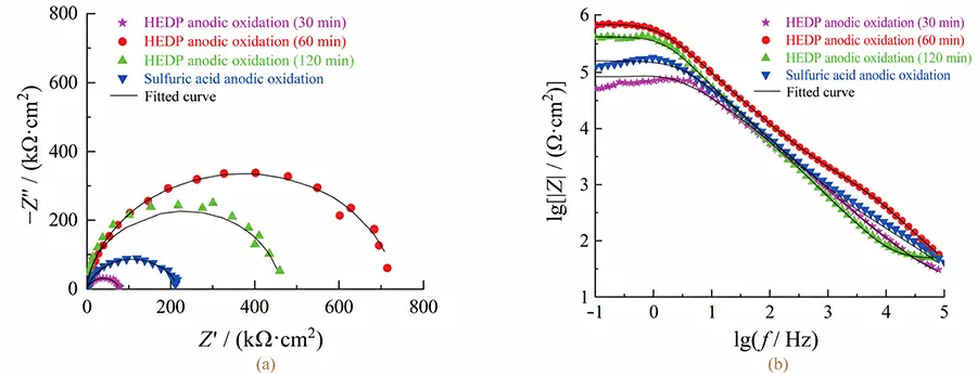
As shown in Figure 5a, the electrochemical impedance spectra of all anodized coatings exhibit a capacitive-reactive arc.
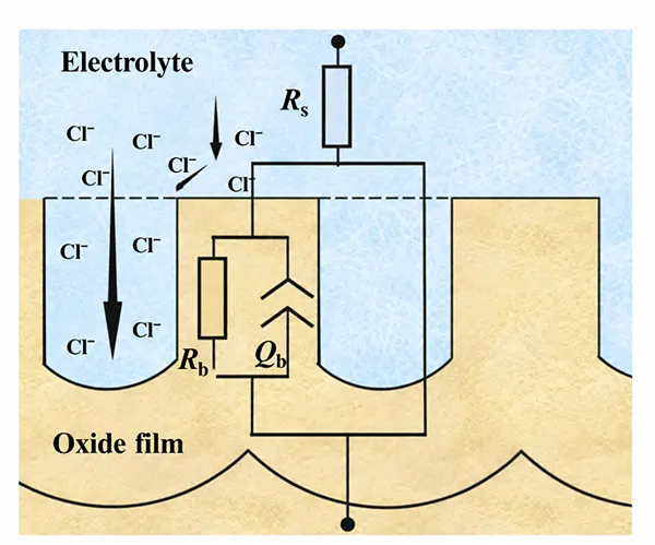
Analysis suggests that the HEDP and sulfuric acid-anodized coatings have larger pores, allowing corrosive Cl− ions to easily pass through the porous layer and reach the barrier layer directly.
Consequently, we can only detect information from the barrier layer in the impedance spectra, so we observe a single capacitive-reactive arc in the Nyquist plot.
Figure 5a displays the capacitive arcs of different anodic oxides with varying radii, and Figure 5b gives their low-frequency impedance values. The impedance magnitudes differ greatly between these samples.
Hitzig et al. proposed that the mid-to-high-frequency region in the Bode plot mainly corresponds to the porous layer of the anodic oxide film, while the low-frequency region is associated with the barrier layer.
On this basis, we conclude that oxide films prepared with different anodizing systems and process parameters show obvious discrepancies in barrier layer resistance.
Based on the above analysis, the oxide film was modeled using the equivalent circuit shown in Figure 6, where Rs is the solution resistance, Rb is the equivalent resistance of the barrier layer, and Qb represents the non-ideal capacitance of the barrier layer, the value of which can be calculated using Equation (2).
Q=Y0-1/(jω)n (2)
In this equation,
The closer the value of n is to 1, the closer the behavior is to that of a pure capacitor.
As shown by the fitting results in Table 2, there are significant differences in the equivalent resistance (Rb) of the barrier layer in HEDP oxide films formed at different oxidation times.
The Rb value of the oxide film formed after 60 minutes of oxidation is the highest and is more than three times that of a sulfuric acid oxide film of the same thickness.
Based on this, we conclude that the HEDP oxide film formed after 60 minutes of oxidation delivers the best corrosion resistance and outperforms a sulfuric acid oxide film of the same thickness by a large margin.
In addition, the n-values of the barrier layers in the different oxide films also vary;
The HEDP oxide film produced after 60 minutes of oxidation has an n-value as high as 0.935, which further indicates that the barrier layer of this oxide film is the densest and most intact.
We often relate the corrosion resistance of porous anodic oxide films to factors such as film thickness, pore size, and barrier layer structure.
When the film is relatively thin and the pore size is large, the corrosive medium can easily penetrate the porous layer, and the film’s corrosion resistance depends to a greater extent on the barrier layer.
After 30 minutes of anodization, the HEDP oxide film was generally thin, and the barrier layer had limited thickness; Therefore, the corrosion resistance of the specimens was poor.
As the oxidation time increases, the HEDP anodic oxide film gradually thickens, and the barrier layer becomes thicker. A thicker film (including the porous layer) can delay the onset of corrosion to some extent and improve the film’s corrosion resistance;
However, corrosion resistance remains primarily dependent on the barrier layer. At oxidation times of 60 min and 120 min, the barrier layer thickness of the HEDP oxide film was comparable;
However, after 120 min of oxidation, the pore size of the film increased to 180–190 nm, resulting in a decrease in corrosion resistance compared to the 60-minute oxidation treatment.
We compare HEDP-oxidized films and sulfuric acid-oxidized films with the same thickness. The HEDP-oxidized film has a larger pore size.
However, its barrier layer is much thicker. This is compared with the sulfuric acid-oxidized film (see Section 2.2.2). Therefore, the HEDP-oxidized film shows better corrosion resistance.
| Passive Oxide System | Oxidation Time (min) | \(R_b\) (kΩ·cm²) | \(Q_b\) (Ω⁻¹·cm⁻²·sⁿ) | \(n\) |
|---|---|---|---|---|
| HEDP | 30 | 178.1 | 1.289 | 0.864 |
| HEDP | 60 | 740.3 | 0.311 | 0.935 |
| HEDP | 120 | 461.5 | 0.438 | 0.901 |
| Sulfuric acid | 30 | 218.4 | 0.638 | 0.863 |
Table 2. Fitting results of electrochemical impedance spectra for different anodized specimens
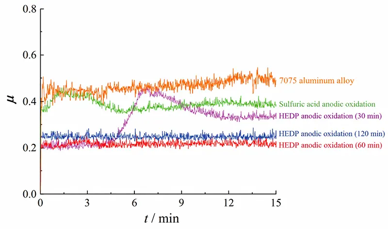
As shown in Figure 7, the coefficient of friction (μ) of the 7075 aluminum alloy substrate is high and unstable, fluctuating between 0.35 and 0.50, with a wear rate as high as 5.71 × 10⁻⁴ mm3/(N·m).
After anodizing, the coefficient of friction of the 7075 aluminum alloy decreased significantly and became more stable;
However, the wear resistance of the oxide film is closely related to the anodizing system and parameters. The HEDP oxide film was prepared by anodization for 30 min. This film was relatively thin.
It was quickly worn through under friction. As a result, its friction coefficient rose rapidly at about 5 min. Its wear rate was close to that of the 7075 aluminum alloy substrate. The HEDP oxide film gradually thickened with increasing anodizing time, resulting in improved wear resistance.
As shown in Figure 7, the coefficient of friction for the HEDP oxide film at 60 and 120 minutes of anodizing was as low as 0.20–0.25 with minimal fluctuation, and the wear rates were 9.59 × 10^(−5) mm³/(N·m) and 1.92 × 10^(−4) mm³/(N·m), respectively.
Furthermore, Figure 7 shows that the friction coefficient curve of the HEDP oxide film is generally lower than that of the sulfuric acid anodized film, and the wear rate is also lower;
In particular, the wear rate of the HEDP oxide film after 60 minutes of oxidation is only 36% of that of the sulfuric acid anodized film.
Analysis suggests that the 7075-T6 aluminum alloy has relatively low hardness (approximately 150 HV), and during friction, adhesive wear occurs alongside abrasive wear, resulting in a highly unstable wear process.
After anodizing, a layer of Al₂O₃ film forms on the surface of the 7075 aluminum alloy, significantly increasing surface hardness and reducing adhesive wear.
However, differences in the thickness, microstructure, and hardness of the anodized films result in varying levels of wear resistance.
We measured a slightly lower hardness (approximately 280 HV) for the sulfuric acid anodized film, and it offers limited resistance to external forces.
Therefore, its wear resistance is relatively poor. The HEDP anodizing time is short, such as 30 min. The oxide film is thin. It cannot well resist the damage from external stress.
The film peels off from the surface. Abrasive particles form at the friction interface. This leads to a slightly higher friction coefficient.
As the anodizing time increases, the thickness of the oxide layer increases, and the hardness of the HEDP oxide layer rises (562–589 HV).
A thicker, harder oxide layer further enhances the layer’s ability to resist external forces, reduces the shear stress experienced during friction, and thereby minimizes wear on the layer.
Among these, the HEDP oxide layer anodized for 60 minutes exhibits a microhardness as high as 589 HV and superior wear resistance.
1) HEDP anodizing is a typical porous anodizing system; the anodic oxide film exhibits a bilayer structure consisting of a porous layer and a barrier layer.
However, the thickness of its barrier layer is significantly greater than that of sulfuric acid anodized films, and the surface pore size is also larger.
As the anodizing time increases, the pore size of the oxide film becomes larger, and the orderliness of the micropore arrangement increases, but the thickness of the barrier layer remains essentially constant at 250–270 nm.
2) We relate the corrosion resistance of the HEDP anodized coating to factors such as coating thickness, pore size, and barrier layer structure.
Appropriately extending the anodizing time increases both the total coating thickness and the barrier layer thickness, thereby enhancing the coating’s corrosion resistance.
When anodized for 60 minutes, the HEDP anodic coating reaches a thickness of 13 μm with a barrier layer thickness of 274 nm, exhibiting optimal corrosion resistance;
Its corrosion current density is only 10% of that of a sulfuric acid anodic coating of equivalent thickness.
3) The HEDP anodic coating significantly improves the wear resistance of 7075 aluminum alloy, and overall performance generally improves with longer anodizing times.
We found that the HEDP oxide film formed after 60 minutes of oxidation exhibited a low coefficient of friction of 0.20–0.25 and a wear rate of only 9.59 × 10⁻⁵ mm³/(N·m). We attribute its best wear resistance mainly to the film’s high hardness.