How to efficiently machine shaped parts on CNC mill-turn machines?


With China’s manufacturing sector rapidly evolving toward high precision and high efficiency, modern smart manufacturing technologies have advanced by leaps and bounds.
CNC milling machines represent core equipment in modern manufacturing; their quality and efficiency hinge directly on the rationality of fixture design.
Serving as the critical interface linking workpieces to machine tools, fixtures influence not only machining accuracy and stability but also production costs and lead times.
However, traditional fixture designs have several drawbacks. They produce large positioning errors and lack flexibility.
These features make it hard to satisfy the requirements of high-variety, low-volume production.
Therefore, the design and optimization of fixtures for CNC milling machines are of great importance.
Fixtures are process tools used in mechanical manufacturing to position, clamp, and secure workpieces, providing effective positioning and stabilization.
In daily manufacturing operations, fixtures can improve the quality and efficiency of CNC milling machines while reducing the rate of defective products.
The higher the precision of the workpiece, the greater the demands placed on the fixtures.
Since milling machines perform machining using cutting tools, which generate significant cutting forces, the requirements for fixtures are even higher.
Traditionally, fixtures used for milling machines generally include screw clamps, clamping plates, and cam clamps.
Operators must tighten all screw clamps of various sizes 90° with a tool (90° is the standard operating procedure).
Workers must apply surface treatment to clamping plates, and install protective material on the plates’ surfaces during operation to prevent damage. Clamping plates are a common type of fixture.
Cam clamps have several limitations. Their instability limits their self-locking capability, so engineers should not use them under certain operating conditions.
These fixtures represent the accumulated achievements of the manufacturing industry over many years and are capable of meeting most routine manufacturing needs.
The core function of a fixture is to keep the workpiece securely in place throughout the entire machining process.
Therefore, the fixture must have sufficient load-bearing capacity and be suitable for various machining conditions.
Designers must incorporate soft contact surfaces or cushioning structures into the design to prevent damage to the workpiece surface.
Engineers should select high-strength materials or specially treated materials for high-stress applications to enhance wear resistance.
Designers should maintain manufacturing tolerances for the fixture as tightly as possible and consider the workpiece’s precision requirements during the design phase to avoid exceeding tolerances.
Additionally, designers must account for cost-effectiveness while ensuring functionality.
Teams should prioritize design solutions with simple structures that are easy to maintain and replace to balance production efficiency and economic viability.
Analyze the machining requirements of the workpiece.
Analyze the workpiece shape, dimensions, precision requirements and milling operations.
Identify the degrees of freedom the fixture needs to restrict.
Determine the positioning references. Define the points and directions of clamping force.
Choose suitable positioning elements. Examples include locating pins, locating blocks and V-blocks.
These elements position the workpiece correctly inside the fixture. They also satisfy six-point positioning rules.
Evaluate milling force magnitude, cutting direction and workpiece rigidity.
Select or combine helical clamping elements, clamping plates, cam clamping elements and other parts.
The clamping system must hold the workpiece reliably. It must not deform the workpiece.
Arrange locating elements, clamping elements, tool-setting elements and guiding elements reasonably.
Finish the fixture body design. Ensure the fixture connects firmly to the machine tool table.
In terms of manufacturing processes, special attention should be given to material selection.
Choose materials with stable mechanical properties for the fixture body and key positioning elements.
Carry out necessary heat treatment. The heat treatment removes internal stresses and improves wear resistance.
Create a machining process plan for the fixture. Include finishing operations for critical surfaces.
These operations guarantee compliance with geometric and positional tolerances.
Inspect and monitor the fixture’s key dimensions and fit clearances during machining.
Make sure the machining accuracy meets requirements.
Improve the rationality of the machining process.
Use efficient algorithms to calculate tool setting points.
These points serve as the positioning references needed for part machining.
The algorithms simplify alignment operations after setting machining offsets.
They support subsequent quality inspections. They also reduce errors to the greatest extent possible.
Reduce manufacturing complexity. Process design requires the calculation and conversion of relevant data.
For example: mechanical analysis is used to determine the clamping force of the fixture, avoiding clamping that is too loose or too tight;
Coordinate conversion is employed to align the machining reference with the fixture reference, thereby reducing tool setting errors;
And simulation software is utilized to perform stress analysis, predicting the deformation trends of the fixture during machining to optimize its structure.
Select cutting tools accurately.
During the design process of tooling and fixtures for CNC milling machines, first select cutting tools based on their characteristics and machining performance;
Then, consider the part’s machining position on the milling machine and mount the tools in the optimal machining position to prevent tool collisions.
Operators must follow process specifications and must not alter cutting parameters without authorization to avoid compromising machining accuracy.
Adopt a step-by-step machining strategy for critical processes.
First, conduct rough machining to remove excess material.
Next, carry out finish machining to guarantee dimensional accuracy.
This method prevents workpiece deformation and rapid tool wear from excessive cutting forces.
Plan the machining sequence following three principles:
Machine reference surfaces first, rough before finish machining, and primary features before secondary features.
Prioritize the accuracy of reference surfaces. Use these reference surfaces to machine other features.
Use a reasonable clamping sequence for complex workpieces.
This approach avoids cumulative errors. Such errors arise from repeated positioning or uneven clamping forces.
During rough machining, if it is necessary to ensure production efficiency and reduce costs, the cutting volume may be increased.
For finish machining, analyze whether the fixture’s accuracy meets the machining requirements and select a more suitable fixture to improve practical results.
CNC milling machines typically use an air compressor to compress air into compressed air at a specific pressure.
Using compressed air as a power source enables automatic tool changing.
During the machining process, tool changing allows for the sequential machining of various surfaces;
However, automatic tool changing is prone to malfunctions, and each tool change takes a relatively long time.
To reduce tool-change time, the number of tool changes can be minimized—provided that the machining requirements of the workpieces are met.
By clamping multiple workpieces in a single setup, the number of tool changes is minimized while ensuring machining quality.
Based on the workpieces’ machining dimensions and shapes, and taking into account the machine tool’s travel range, the setup was designed to clamp eight workpieces at a time.
A schematic diagram showing the layout of the multi-workpiece clamping stations is shown in Figure 1.
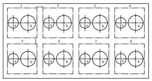
The improved work process is as follows: Install the reamer for hole a, then ream holes a in workpieces 1 through 8 in sequence;
Replace the reamer with a reamer for hole a, and ream in the same order;
Repeat the procedure for hole b as for hole a.
During the setup process, pay attention to clamping requirements and workpiece positioning.
As shown in the above workflow, only four tool changes are required per operation to complete the machining of all eight parts, which significantly improves work efficiency.
Arrange workpiece positions properly. Base the layout on the workpiece precision requirements and outer dimensions.
Consider the working stroke and table size of the CNC milling machine. Also take the production batch into account.
Set a moderate spacing between workpieces.
This layout maximizes the number of workpieces clamped in one setup and improves machining efficiency.
It also supports easy workpiece loading, unloading and chip removal.
Leave enough clearance during fixture design. This design allows centralized machining.
It reduces contact between the fixture and moving components.
The arrangement prevents equipment malfunctions.
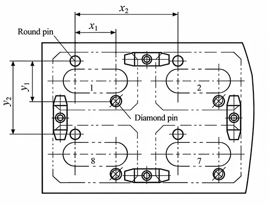
Second, the relative distances between positioning elements must maintain high dimensional accuracy to ensure consistency of the positioning reference.
The multi-workpiece fixture employs a combination of cylindrical and diamond-shaped pins for positioning.
Control the spacing (x1, y1) between the cylindrical pin and diamond pin in each positioning set.
Also control the spacing (x2, y2) between different positioning sets.
Strict dimensional control keeps workpieces in precise machining positions throughout milling.
A schematic diagram of the positioning elements for the multi-workpiece fixture is shown in Figure 2.
Third, the clamping method must be appropriate.
Design clamping elements for easy installation and removal.
This simplifies later maintenance and part replacement. Reserve enough operating space for milling cutters to avoid tool collisions.
Let each clamping plate hold two workpieces. Multiple clamping elements work at the same time.
This reduces the total number of clamping parts while maintaining sufficient clamping force.
Manufacturers often use process consolidation on CNC milling machines in actual production.
The method raises efficiency and cuts production costs. It blurs the boundary between rough machining and finish machining.
To ensure proper machining, clamping force is generally set to a high level; however, this can damage the workpiece surface.
Therefore, before machining begins, the clamping plates should be treated by adding soft protective material.
During machining on vertical CNC milling machines, chip buildup is a key factor affecting machining accuracy, tool life, and machining efficiency.
A vertical milling machine has a vertically downward spindle.
Chips easily build up on workpiece surfaces, fixture locating surfaces, and guideways.
This accumulation creates several problems. Chip buildup shifts the workpiece position. It reduces machining stability.
Secondary cutting of chips accelerates tool wear and may even cause chipping;
And stopping the machine to clear chips disrupts machining continuity and reduces production efficiency.
Optimize the chip removal system during fixture design for vertical milling machines.
The system discharges chips smoothly and efficiently. It maintains fixture positioning accuracy and machining stability.
First, reduce the contact area between chips and the fixture by adopting an open structure and avoiding the use of enclosed fixtures to minimize dead spots where chips can accumulate.
For example: Use perforated support plates or lattice-style clamping bodies to allow chips to fall naturally;
Use V-block pins for positioning to avoid flat contact surfaces between the fixture and the workpiece, thereby reducing chip retention.
Second, install angled chip-removal grooves at key locations on the fixture to guide chips to the chip-removal area.
At the same time, install air nozzles on the fixture to automatically blow away chips during machining pauses or tool changes, and use cutting fluid to flush the workpiece or fixture.
Install quick-release protective covers on chip accumulation areas of the fixture.
These covers stop chips from entering precision components.
Alternatively, use magnetic shields to block flying chips. The measures maintain stable and efficient machining.
First, regarding toolpaths, prioritize up-milling to direct chips toward unmachined areas, thereby reducing the likelihood of chip buildup on the fixture.
Second, increase the feed rate to produce shorter chips that break more easily, reducing the risk of tangling; reduce the depth of cut to prevent the formation of excessively long ribbon-like chips.
Third, install an automated chip removal system beneath the machine tool table.
This system, working in conjunction with the chip slots in the fixture, enables continuous chip removal, with a robotic arm automatically clearing residual chips from the fixture and work surface during machining pauses.
This not only improves machining efficiency and workpiece quality but also extends the service life of both the fixture and the cutting tools.
When machining workpieces on a CNC milling machine, tooling and fixtures are required to assist with positioning and clamping to ensure machining quality and efficiency.
The rationality of the fixture design and the effectiveness of any improvements are directly reflected in the machining process of the CNC milling machine.
An efficient and well-designed fixture can maximize the performance of the CNC milling machine;
Its design must prioritize clamping processes, securing methods, and tool setting techniques, while maintaining sufficient accessibility to ensure a continuous and stable machining process.
The fixture discussed in this article employs a structure that allows for the clamping of multiple workpieces in a single setup.
Combined with a multi-station design, it effectively addresses the issues of low efficiency and high costs encountered in actual production.
In practical manufacturing, designers and operators should collaborate to develop simpler and more practical fixtures based on specific requirements, thereby reducing operational workload and safety risks.