What impact does CNC tool selection have on the CNC machining process?


A bearing anti-rotation lug primarily restricts circumferential rotation of the bearing outer or inner ring. It prevents torque-induced relative slippage during operation. It maintains stable power transmission and load bearing for the bearing.
It typically fits into a groove on the bearing housing or shaft, forming a “mortise-and-tenon joint”—much like adding a “locating pin” to the bearing—to prevent positional displacement caused by vibration, impact, or other factors.
Technicians originally machined the anti-rotation lugs and grooves with the CNC system’s built-in macros.
Years of experiments show that CNC macros are inherently abstract. The dimensions of the anti-rotation structure vary by model.
Programmers frequently introduce programming mistakes. These mistakes can cause tool collision risks.
Without macro simulation, it was difficult to guarantee the safety of toolpaths. UG is a well-known software package commonly used in the aerospace industry.
Users perform CNC programming in UG. They can intuitively check product structures, dimensions, and toolpath designs.
The software helps avoid programming errors. It guarantees the safety of auto-generated CNC programs.
To ensure the dimensional accuracy of the anti-rotation structure, operators generally schedule machining after heat treatment and final grinding of both end faces, but before grinding the boss end face and fine lapping both end faces.
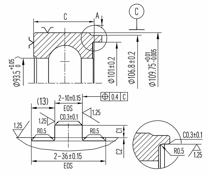
| Measurement Item | Value (mm) | Measuring Tool |
|---|---|---|
| End-face height C | 22.15 ± 0.03 | — |
| Boss height C1 | 1.55 ± 0.15 | — |
| Groove depth C2 | 1.15 ± 0.15 | — |
| Boss length | 2–10 ± 0.15 (EQS) | Caliper |
| Boss inner diameter | Ø101 ± 0.2 | — |
| Groove width | 2–36 ± 0.15 (EQS) | — |
| Transition radius R | R0.5 | Template |
| Positional tolerance | 0.4 | Coordinate measuring machine (CMM) |
| Surface roughness Ra (between processes) | 1.25 | Comparison sample block |
| Chamfer | C0.3 ± 0.1 | Coordinate measuring template |
Table 1. Measurement Items for the Anti-Rotation Structure
Engineers primarily create solid models using the software’s solid modeling functions — such as rotation, extrusion, and subtraction — based on the workpiece cross-section sketch, as shown in Figure 2.
When modeling, it is best to ensure that the workpiece origin (the center of the boss top surface) and the solid model origin, as well as the machining reference (the boss top surface) and the model reference, coincide.
This avoids the need to adjust the machining coordinate system during programming due to a mismatch between the modeling reference and the machining reference. Improve programming efficiency.
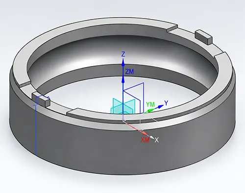
The built-in anti-rotation mechanism typically consists of two base planes (the bottom surface of the groove and the bearing end face).
Operators achieve automatic programming in UG by manually defining the tool centerline and performing plane milling.
Priority order for milling the groove and the end face. Milling the bottom of the groove and the bearing end face are parallel operations.
In practice, the setup involves milling the bottom of the groove first, followed by the bearing end face—that is, first machining the C2 groove depth, then machining the C boss height.
Researchers selected a standard Φ12 mm end mill to control tooling costs, avoid interference with the 13 mm groove width, and ensure adequate machining efficiency.
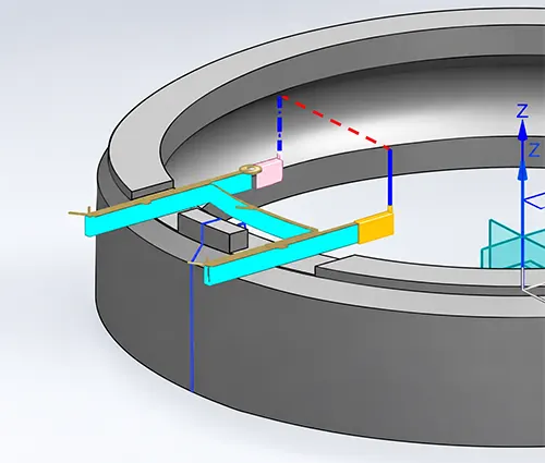
As the light red line in Figure 3 shows, researchers created a sketch contour as the tool centerline and positioned this tool centerline 6 mm away from the edges on both sides of the boss.
With a groove width of 13 mm, radial cutting with a Φ12 cutter requires two passes to complete.
Additionally, to ensure uniform machining marks on the groove bottom surface, the distance between the tool centerline’s entry and exit points and the workpiece must be greater than the tool radius.
Since the inner surface of the boss is curved, users maintain a 6 mm distance between the tool centerline and the boss’s inner surface.
For this model, the center radius of the tool path for milling the inner arc of the boss is 44.5 mm.
Engineers recommend selecting the top surface of the boss as the reference plane for the sketch.
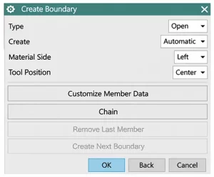
Select the 2.5-axis planar milling function in the software. Specify the part boundary by selecting the edited sketch—the contour tool center path.
Under “Boundary Type,” select “Open.” For “Tool Position,” select “Centered.” For “Base Surface,” select the bottom surface of the groove generated by the modeling process.
Select “Contour Machining” as the cutting mode.
Since operators machine the bearing ring after heat treatment, they limit the depth of each cutting pass.
Considering both machining efficiency and tool life, engineers recommend an empirical value of 0.10–0.20 mm.
Because the part has only one bottom surface, users can select either “Layer Priority” or “Depth Priority” as the strategy in the cutting parameters.
For non-moving cutting, select “Linear” for open areas and “None” for closed areas.
Since there is no interference from positioning fixtures between the two grooves, and to minimize the idle path, set the distance from the entry point to 3 mm in length and 3 mm in height, with a minimum safety distance of “None.”
The retract path is the same as the entry path. Set the spindle speed to 3,000 r/min and the feed rate to 220 mm/min.
In Figure 3, the dark blue dashed line indicates rapid positioning to the starting point; the orange toolpath represents the starting and approach paths;
The light blue toolpath represents the cutting path; the pale pink toolpath represents the retraction and lift-off paths; and the red dashed line indicates rapid positioning.
The edges of the boss’s outer diameter (C0.3±0.1) are deburred by turning, while the sides of the boss (C0.3±0.1) are deburred using a 90° chamfering end mill, ensuring uniform and consistent product appearance.
The transition radius (R0.5) at the bottom of the groove is achieved using the end mill’s cutting edge.
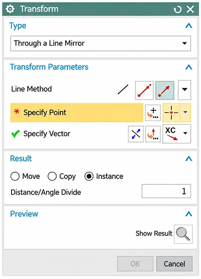
By selecting a generated single-structure toolpath and using Object-Transform to array the toolpaths, as shown in Figure 5 [Example], the selected toolpaths will remain linked to the source toolpath after arraying.
This reduces the need for manual editing of identical toolpaths.
The wall thickness on one side of the bearing outer ring boss—which features an anti-rotation mechanism—is only (φ106.8 – φ93.5)/2 = 6.65 mm.
As shown in Figure 1, the tool center path on the outer ring end face should follow the geometric center of the single-side wall thickness of the boss.
Users can select geometric constraints such as “Midpoint” or “Concentric” within the sketch.
The distance between the tool entry and exit points and the cutting start (or end) point must be greater than the sum of the single-side wall thickness of the outer ring and the tool radius.
In this example, users specify the tool entry and exit path distances as 15 mm.
The complete toolpaths for the generated milled groove (boss) and milled boss face (bearing end face) are shown in Figure 6.
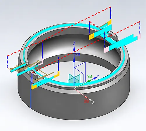
Researchers generate multi-layer toolpaths through solid modeling, manual design of single-layer toolpaths, and automated software calculations.
This method makes automatic programming error-proof, intuitive, and computationally efficient.
Machinists grind and superfinish the two positioning or assembly end faces of bearing rings. This step maintains accurate bearing positioning and assembly during use.
It meets the workpiece operational requirements when forming the product structure.
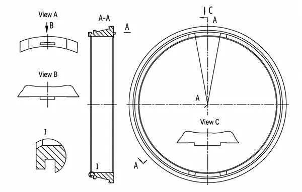
The inner ring of a certain tapered roller bearing, as shown in Figure 7, features anti-rotation (stop) lugs and grooves on both end faces.
When interpreting the drawing, special attention must be paid to the one-to-one correspondence between the views.
This workpiece has anti-rotation boss and groove structures on its large end face.
These structures match the views in directions A and B of the detailed drawing. The small end face also has anti-rotation boss and groove structures.
They match the view in direction C of the detailed drawing.
The front view depicts the structure of the smaller end face, not that of the larger end face.
The ability to visualize spatial relationships in drawings (and accurately identify correspondences between views) is an error-prevention skill for CNC programmers.
Users transform abstract two-dimensional plan views into intuitive three-dimensional spatial views during the modeling process in UG.
This intuitive modeling approach makes software-based programming more error-resistant than manual programming.
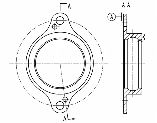
To ensure a secure connection between the external structure and the bearing and to precisely define the bearing’s radial and axial positions, the outer ring structure of a bearing with a mounting flange is shown in Figure 8.
The centerlines of the large and small holes on the mounting flange form a certain angle.
The product design datum is Surface A (the large end face);
To reduce the tool overhang and increase the rigidity of the machining system, the small end face is used for positioning during machining.
When programming (modeling), operators should note that the left-right orientation in the front view reverses when the large end face sits at the top and the small end face at the bottom.
Operators position the workpiece on a dedicated mandrel using its inner diameter and small end face.
While prioritizing programming efficiency and omitting fixture modeling, care must be taken to ensure that toolpaths do not interfere with the mandrel (fixture).
Engineers use UG to implement automated CNC machining for aviation rolling bearings with built-in anti-rotation mechanisms.
This method satisfies process design requirements. It also cuts down the complexity and calculation workload of manual programming.
This programming method is easy to set up and intuitive to operate, offering features such as high computational efficiency, strong error-proofing capabilities, and a high level of machining safety.