How to efficiently machine shaped parts on CNC mill-turn machines?



Many newcomers to the CNC machining industry often find it hard to distinguish between 3-axis, 3+2-axis, and 5-axis machining methods.
In fact, it’s not just beginners—even those with years of experience in the industry sometimes struggle to tell them apart.
This article provides a detailed summary of the key points, so be sure to check it out!
3-axis machining is performed using the linear feed axes X, Y, and Z. Key feature:
The direction of the cutting tool remains constant throughout the entire cutting path.
It is impossible for the cutting condition at the tool tip to be perfect at all times.
Two rotary axes first fix the cutting tool at an inclined position, and then machining is performed using the feed axes X, Y, and Z.
This type of machine tool is also known as a positioning 5-axis machine.
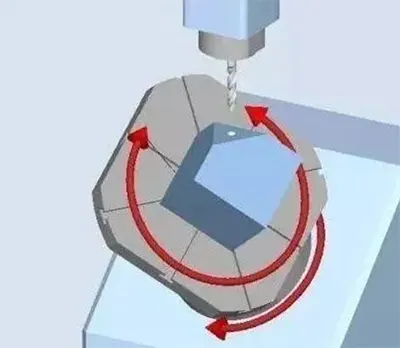
CYCLE800 is a static plane transformation that allows you to define a rotating work plane in space using a 3+2-axis machine (such as a rotary head or rotary table).
Within this work plane, you can program 2D or 3D machining operations.
Machining Characteristics:
Operators always rotate the rotary axis to a position where the machining plane is perpendicular to the tool axis, and the machining plane stays fixed during machining.
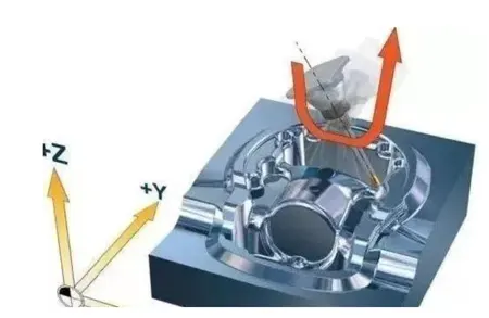
5-axis machining involves linear interpolation movements of any five axes selected from the feed axes X, Y, and Z, and the rotational axes A, B, and C around the X, Y, and Z axes. Siemens’ motion conversion command TRAORI provides excellent support for 5-axis conversion.
Machining Features:
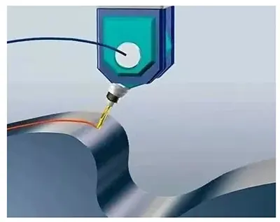
We can optimize the tool orientation throughout the entire path while the tool moves in a straight line.
This ensures we maintain optimal cutting conditions along the entire path.
How does the 5-axis machine demonstrate its advantages? Here’s an example of a Haas UMC-750P machine simultaneously machining 28 parts.
Through the design of the rotary table and fixtures, and by combining the three machining surfaces of each part into a single machining program, the machine achieves the goal of reducing cycle time.
The rotary table expands the original machining space through precise positioning.
The carefully designed fixture not only improves machining efficiency but also reduces machine downtime, freeing up operators to focus on other tasks.
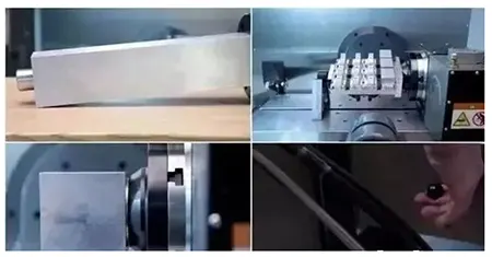
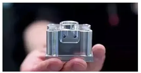
For example, to machine the first three surfaces of a part like the one shown below, using a vise clamping method would take a total of 264 seconds per part (excluding setup time).
By designing a more compact fixture that makes full use of the machining space provided by the rotary table, it is possible to machine 28 parts in a single operation.
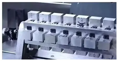
We selected a 114 mm × 114 mm × 550 mm aluminum alloy block as the base for the fixture.
We used locating pins for positioning and chose a clamping fixture with smaller machining space occupation to speed up setup.
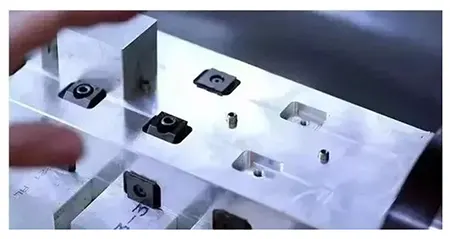
Next, mill the four faces of the blank flat, machine a locating pin hole for each part, two slots for the locking fixture, and two threaded holes for clamping—that’s all there is to it.
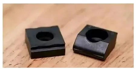
The complete set of fixtures includes: 28 positioning pins, 56 positioning locking blocks (reusable), 56 screws, and a wrench.
This fixture design reduces the original machining time from 264 seconds to 202 seconds (excluding setup time). This represents a 23.5% reduction in machining time.
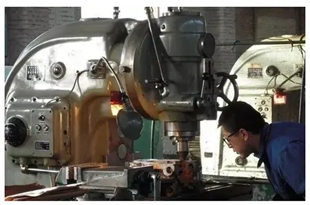
Not only that, but since the machining program has combined the three machining surfaces of the part into a single program, the cycle time for that program is now 95 minutes.
During this time, the machine continues to machine the part without requiring frequent setup by the operator, which will significantly reduce the operator’s workload.