How to efficiently machine shaped parts on CNC mill-turn machines?



Aerospace equipment is developing toward higher performance and lighter weight. Thin-walled high-temperature alloy components are core parts of aircraft engines.
Their manufacturing precision directly affects the overall performance of the equipment.
Turning-milling composite machining technology has become the primary machining method due to its combination of high efficiency and flexibility;
However, the low stiffness of thin-walled structures and the difficulty in machining high-temperature alloys pose severe challenges to precision control.
We urgently require higher machining accuracy for turning-milling composite machining of thin-walled high-temperature alloy components.
To meet this demand, this paper develops a systematic method.
This method integrates dynamic stiffness field modeling, coupled prediction of cutting forces and deformation, process parameter optimization, and real-time error compensation.
It further provides solid theoretical support and practical engineering solutions for the high-quality manufacturing of high-end aerospace equipment.
Thin-walled high-temperature alloy parts possess excellent high-temperature mechanical properties and lightweight characteristics.
For this reason, manufacturers widely adopt them to fabricate critical components.
Typical examples include aircraft engine blades and casings.
Combined turning and milling technology, which integrates the high efficiency of turning with the high flexibility of milling, has become the primary machining method for such parts.
However, there are many technical bottlenecks in current machining processes.
High-temperature alloys feature high strength, low thermal conductivity, and severe work hardening.
These properties lead to large cutting forces and serious tool wear.
The low stiffness and frequent cross-sectional changes of thin-walled structures make them prone to elastic deformation and vibration under cutting forces;
Composite turning-milling machining involves multi-axis coordination, tool changing, and dynamic adjustment of process parameters;
Traditional empirical methods for parameter selection struggle to adapt to the time-varying dynamic stiffness characteristics of thin-walled parts;
Existing machining processes lack real-time monitoring and feedback mechanisms, making it impossible to compensate for machining errors online, which results in low first-pass yield and high scrap rates.
To solve the above shortcomings, researchers urgently need to carry out targeted technical research.
It is necessary to establish a dynamic stiffness field model that fully considers material removal effects.
It is also essential to develop a coupled prediction mechanism for cutting forces and machining deformation.
Meanwhile, researchers should formulate an intelligent optimization method for multi-constraint process parameters and construct a real-time monitoring and error compensation system for machining processes.
These efforts can ultimately realize the high-precision and high-efficiency turning-milling composite machining of thin-walled high-temperature alloy parts.
This study aims to satisfy the above technical requirements.
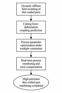
It divides the accuracy improvement method for turning-milling hybrid machining into four core stages.
The first stage is the dynamic stiffness field modeling of thin-walled parts.
The second stage is the coupled prediction of cutting forces and machining deformation.
The third stage is the multi-constraint optimization of process parameters.
The last stage involves real-time machining process monitoring and error compensation.
Dynamic stiffness field modeling constructs a mathematical representation.
It can accurately describe the spatiotemporal distribution characteristics of the stiffness of thin-walled parts.
Furthermore, it lays a structural mechanics foundation for subsequent analytical research.
Cutting force–deformation coupling prediction establishes a mapping relationship between cutting parameters and machining deformation to enable quantitative error prediction;
Process parameter optimization solves for the optimal parameter combination under multi-objective constraints;
Real-time monitoring and error compensation implement online corrections through the acquisition and analysis of sensor signals, forming a closed-loop control system.
The specific workflow is shown in Figure 1.


Thin-walled parts undergo continuous material removal during turning-milling hybrid machining.
This process continuously changes the structural geometry and mass distribution of the parts.
Accordingly, the local stiffness of thin-walled parts presents prominent spatiotemporal coupling characteristics.
This study employs an incremental finite element method to establish a dynamic stiffness field model.
We discretize the machining process into several time steps;
At each step, we determine the material removal region based on the tool path and cutting parameters, and update the finite element model using mesh reconstruction techniques.
At the i-th machining time step, researchers extract the tool position and orientation from the CNC program, calculate the tool sweep volume, delete the corresponding mesh elements, and regenerate the boundary conditions.
Modal analysis is used to extract the natural frequencies and mode shapes of the updated structure.
Combined with unit force loading, researchers obtain the flexibility matrix and use its inverse matrix as the stiffness matrix.
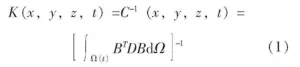
We can express the stiffness field as:
In this equation, B is the strain-displacement matrix, D is the material elasticity matrix, and Ω(t) is the residual material region of the thin-walled component at time t.
The stiffness distribution matrix output by this model provides the fundamental structural mechanics data for predicting the coupling between cutting forces and deformation.
Based on the dynamic stiffness field model established in the previous section, this section develops a mechanism for predicting the coupling between cutting forces and machining deformation.
In the combined turning and milling of superalloys, cutting parameters, tool geometry, and material properties jointly influence cutting forces, and tool motion changes their magnitude and direction in real time.
This study adopts the Kienzle empirical cutting force model as a foundation and, combined with correction factors for the material properties of high-temperature alloys, establishes triaxial cutting force prediction equations.
The principal cutting force Fe, feed force Ff, and back force Fp are related to the depth of cut ap, feed rate f, and cutting speed vc, respectively.
After obtaining the time history of the cutting forces, we apply these forces as loads to the corresponding nodes of the finite element model established in the previous section.
Researchers obtain the displacement responses at various locations of the thin-walled part through a static analysis.
Since cutting-force-induced deformation alters the actual cutting thickness and this change in turn affects cutting force magnitude, researchers must establish an iterative solution framework.
We can express the coupling relationship between deformation and cutting forces as:
In the equation, δ is the deformation vector, kc is the cutting force coefficient, and m1, m2, and m3 are exponential coefficients determined through cutting tests.
This model establishes a quantitative mapping from process parameters to machining deformation, and its prediction results are used as inputs for the objective function in parameter optimization.
Based on the coupled cutting force–deformation prediction model established in the previous section, this section constructs a multi-objective optimization framework to obtain the optimal combination of process parameters.
The optimization objectives include minimizing machining deformation, maximizing material removal rate, ensuring that surface roughness remains within acceptable limits, and ensuring that tool life meets economic requirements.
We represent machining deformation by the maximum deformation value predicted in the previous section;
We characterize material removal rate by the product of cutting parameters;
Surface roughness is determined using an empirical formula relating feed rate and tool tip radius; and tool life is estimated using the Taylor formula.
Constraints include machine tool power limitations, cutting forces not exceeding the tool’s allowable limits, and cutting parameters remaining within the ranges recommended in the process manual.
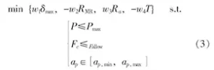
We can express the optimization problem as:
In the equation, w1 through w4 are weighting coefficients, δmax is the maximum deformation, RMR is the material removal rate, Ra is the surface roughness, and T is the tool life;
The constraint conditions ensure process feasibility. The set of optimized parameters is used as the input for the actual machining process.
When we machine workpieces using the optimized process parameters from the previous section, random factors such as tool wear, thermal deformation, and clamping errors may still cause actual machining errors to exceed expectations.
This section describes the development of a real-time monitoring and online compensation system to establish a closed-loop control system.
A three-axis force transducer is used to acquire real-time cutting force signals, a laser displacement sensor measures instantaneous deformation, and an acoustic emission sensor monitors the tool’s condition.
Multi-source sensor signals are synchronously input into the control system, which employs a Kalman filter algorithm to suppress noise and extract characteristic parameters.
We compare the measured cutting force with the predicted value;
If the deviation exceeds a threshold, the system triggers an adaptive parameter adjustment mechanism.
Simultaneously, we calculate the tool path correction based on the actual deformation and an error compensation model.
The compensation strategy employs a predict-and-correct method, and we can express the tool position correction as:
In the equation, △P represents the tool position correction vector, δmeas represents the measured deformation, δpred represents the predicted deformation, and Kp represents the proportional gain coefficient.
The CNC system’s interpolation module updates the corrected tool position coordinates in real time, performing dynamic error compensation to ensure machining accuracy meets design requirements.
Monitoring data is then fed back to the stiffness field model for parameter correction, forming a continuously optimized closed-loop system.
A new thin-walled component was trially produced on the machining production line for thin-walled GH4169 high-temperature alloy casings in an aircraft engine manufacturing enterprise.
The trial production process faced prominent machining problems.
The thin-walled regions of the component produced deformation of 0.15 mm to 0.25 mm.
Meanwhile, the dimensional out-of-tolerance rate of the component reached up to 35%.
The existing process with constant parameters could no longer meet the requirements, so we urgently needed to carry out systematic optimization and upgrade.
The company adopted the accuracy-enhancement method proposed in this study to tackle the process challenges.
Based on the 3D model of the new casing, we established a dynamic stiffness field model.
We divided the machining process into 128 time steps and identified five characteristic regions with significant stiffness variations.
Subsequently, we employed a coupled cutting force–deformation prediction model;
When traditional process parameters were input, the model predicted a maximum deformation of 0.21 mm, thereby verifying the cause of the dimensional deviations;
Next, a multi-objective optimization algorithm was run to derive differentiated parameter combinations for each of the five stiffness zones;
We integrated a real-time monitoring module into the CNC system.
We collected experimental data using a triaxial force gauge and a laser displacement sensor.
These data support the implementation of online error compensation with a fixed compensation cycle of 0.2 s.
This method realizes a tool position correction accuracy of 0.01 mm.
Finally, a complete closed-loop control system is successfully established.
After implementing the method proposed in this study, we compared and verified the machining results before and after optimization.
We selected twelve new thin-walled engine casings for testing and summarize the comparison results of key indicators in Table 1.
表1
As shown in Table 1, the maximum deformation after optimization decreased from 0.22 mm to 0.06 mm—a reduction of 72.7%—successfully controlling machining errors within the ±0.08 mm tolerance range;
The dimensional compliance rate increased from 65% to 95%, making the new product ready for mass production;
Surface roughness improved from Ra 1.8 μm to Ra 1.2 μm, a 33.3% improvement;
Overall production efficiency increased by approximately 40%; tool life extended from 8 parts to 15 parts, representing an 87.5% improvement.
In-depth analysis indicates that implementing a differentiated parameter strategy across the five stiffness zones yielded significant results: a small cutting depth of ap = 0.15 mm was used in the thin-walled areas, effectively suppressing tool deflection;
A large cutting depth of ap = 0.5 mm was used in the thickened areas, ensuring machining efficiency.
The real-time monitoring system captured abnormal cutting force fluctuations at three key time steps, namely 3, 7 and 11.
It automatically activated corresponding parameter correction operations.
We recorded the average compensation response time as 0.18 s.
These results verify the excellent rapid response capability of the established closed-loop control system.
This study focuses on the precision control difficulties in the turning-milling composite machining of thin-walled high-temperature alloy components.
This work proposes a novel closed-loop control method.
This method integrates multiple core technologies, including dynamic stiffness field modeling, coupled prediction of cutting forces and deformation, process parameter optimization, as well as real-time monitoring and error compensation.
We conducted engineering validation on a thin-walled GH4169 engine casing and reduced the maximum deformation by 72.7%, raised the dimensional compliance rate to 95%, and improved overall production efficiency by 40%.
Future work should focus on deepening the integration of intelligent sensing and adaptive control, expanding the method’s applicability, and advancing digital twin-driven machining process optimization.

