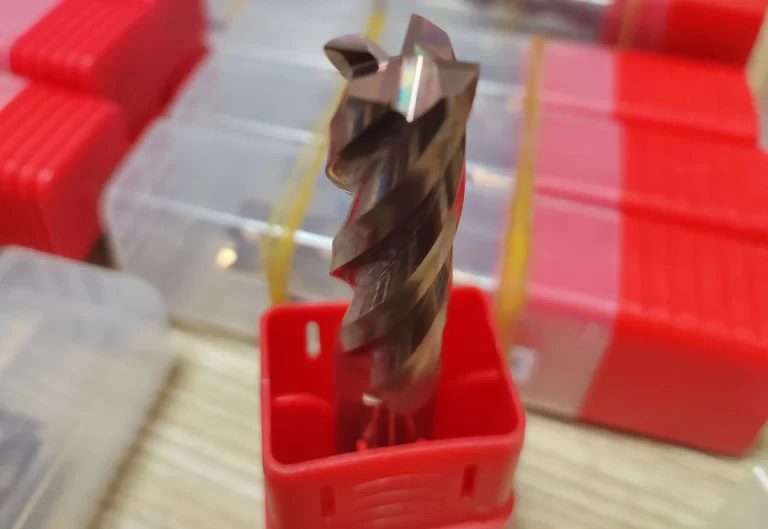
How to efficiently machine shaped parts on CNC mill-turn machines?



The automotive industry continues to demand higher precision and efficiency in mold manufacturing. Modern automotive panels increasingly feature complex shapes and continuously changing surfaces.
Engine components also require finer structural details. Traditional three-axis CNC machining struggles with complex freeform surfaces, deep cavities, and inclined features.
Common problems include poor tool accessibility, low machining efficiency, and unstable surface quality. Five-axis machines add two rotary axes to overcome these limitations.
The additional axes allow the tool to approach the workpiece from different angles. This capability makes complex geometric features easier to machine.
Advances in RTCP technology and intelligent control algorithms have further improved five-axis machining. The technology now offers strong potential for modern automotive mold manufacturing. :chatgpt-content-reference{index=”0″}
Five-axis CNC machines add two rotary axes to the conventional three linear axes. This configuration enables precise tool positioning and orientation in three-dimensional space.
Rotational Tool Center Point, or RTCP, is a core function of this technology. It calculates tool-length compensation vectors in real time to keep the tool tip on its programmed path.
The five-axis system uses tool-axis vector interpolation to establish a local rotational coordinate system. During interpolation, the tool-axis vector remains within a defined plane.
This plane contains the tool-axis vectors at the start and end of each program segment. The method therefore enables smooth changes in tool orientation.
Compared with three-axis machining, five-axis machining reduces tool interference and repeated workpiece setups. It also improves the efficiency and accuracy of complex-surface machining.
By optimizing the relative position between the tool and workpiece, the technology supports challenging mold features. These include deep cavities, inclined surfaces, and freeform surfaces. :chatgpt-content-reference{index=”1″}
RTCP is one of the core technologies used in five-axis simultaneous machining. It establishes a local tool-axis vector coordinate system for precise orientation control.
The RTCP algorithm operates according to the tool-axis vector interpolation principle. Real-time interpolation occurs within the plane defined by the start and end tool-axis vectors.
The tool-axis vector coordinate system follows specific mathematical relationships.


Here, us represents the tool-axis vector at the start of the program segment. The symbol ue represents the vector at the segment endpoint.
The symbol v represents the intermediate vector in the rotational coordinate system. The symbol w represents the third axis vector of that coordinate system.
During interpolation, the tool-axis angle and tool-length compensation vector follow a strict linear distribution relationship.

Here, θi represents the interpolated tool-axis angle, while θ represents the total tool-axis angle. The symbol li represents the interpolated tool travel distance.
The symbol L represents the total length of the program segment.
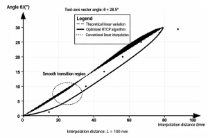
The optimized RTCP algorithm produces smoother angular transitions than conventional linear interpolation. It effectively prevents sudden changes in angular velocity.
The algorithm constructs a tool-length compensation vector plane to maintain a linear relationship during interpolation. This approach significantly suppresses rotary-axis speed jumps and acceleration or deceleration shocks.
As a result, tool orientation remains more stable when machining complex automotive mold surfaces. The method supports precision machining of deep cavities and inclined features. :chatgpt-content-reference{index=”2″} :chatgpt-content-reference{index=”3″}
Rotary-axis movement introduces additional linear motion during five-axis machining, creating nonlinear errors. Linear interpolation in machine coordinates can therefore become a nonlinear spatial curve in workpiece coordinates.
Nonlinear error calculations compare the actual tool-tip trajectory with its theoretical trajectory.

Here, δ(t) represents the nonlinear error in micrometers. The symbol pi(t) represents the actual tool-tip position.
The symbol ps represents the program segment’s starting position, while a represents a unit vector.
The system obtains the actual tool-tip trajectory by transforming machine coordinates into workpiece coordinates.

Here, pxi represents the actual tool-tip position along the workpiece X-axis. Xi, Yi, and Zi represent machine-coordinate positions of the feed axes.
Ai and Ci represent the rotation angles of the rotary axes.
The compensation algorithm calculates nonlinear errors in real time and adjusts tool-path parameters. This method reduces trajectory deviations during large rotary-axis movements.
Consequently, the system improves precision control during automotive mold surface machining. The reported compensation strategy reduced machining errors by 59% compared with the conventional method. :chatgpt-content-reference{index=”4″}
The multi-axis interpolation algorithm coordinates five motion axes to accurately follow complex tool paths. It uses planar tool-axis vector interpolation to control tool orientation.
During real-time interpolation, the tool orientation stays within the plane defined by the endpoint vectors. This approach prevents spatial trajectory distortion associated with conventional linear interpolation.
The optimized algorithm establishes a local tool-axis vector coordinate system and uses proportional interpolation. This strategy produces smoother rotary-axis motion and reduces sudden speed changes.
When machining complex automotive mold surfaces, the algorithm reduces differences between actual and theoretical tool paths. Maximum error decreased from 15 μm to 8 μm.
The method also maintains stable machining across areas with large curvature changes and sharp turns. It provides accurate trajectory tracking for freeform automotive panel mold surfaces.
Optimized interpolation reduces accumulated nonlinear errors and improves tool orientation accuracy. These improvements strengthen five-axis motion control while increasing machining quality and efficiency. :chatgpt-content-reference{index=”5″}
Collision detection uses a tool geometric envelope and workpiece boundary constraints. Together, they enable real-time collision prediction and avoidance during five-axis machining.
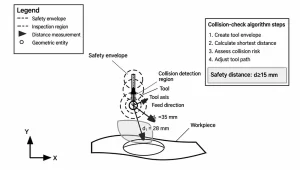
The detection algorithm uses a layered geometric evaluation strategy. It creates a tool safety envelope and multiple detection zones.
The system continuously calculates and monitors the shortest distance between the tool and workpiece. Spatial geometric relationships provide the criteria for collision detection.
When the measured distance falls below a preset safety threshold, the system adjusts the tool path. This mechanism maintains machining safety and continuity.
The technology adapts effectively to deep-cavity machining in automotive molds. It identifies potential interference between the tool holder and cavity walls.
This approach helps prevent overcutting and collisions commonly encountered with conventional methods. The system continuously monitors tool orientation and workpiece geometric constraints.
It also maximizes material removal efficiency while maintaining safe machining conditions. A warning mechanism and multilayer protection strategy provide additional safeguards.
When the tool approaches a hazardous area, the system adjusts its path and orientation parameters. Collision detection therefore reduces scrap and equipment damage risks.
These functions provide reliable protection for efficient machining of complex structures. They also improve the intelligence of five-axis machining systems. :chatgpt-content-reference{index=”6″}
Automotive panel mold machining uses five-axis technology to form complex freeform surfaces accurately. These molds often contain continuously changing surfaces and regions with sharp curvature variations.
Traditional three-axis machining has difficulty maintaining the required surface smoothness and dimensional accuracy. Five-axis machining continuously adjusts tool orientation to overcome these challenges.
The process maintains optimal contact between the tool and machined surface. This approach reduces uneven cusp heights produced by ball-end milling cutters.
The machining process follows layered roughing, semi-finishing, and finishing stages. Roughing uses large-diameter flat-end mills to remove most excess material.
Semi-finishing uses tapered cutters to refine the surface contour. Finishing employs ball-end mills to achieve surface roughness below Ra 0.8 μm.
Tool-path planning combines equidistant offsets with streamline tracking. The system generates smooth paths according to the principal curvature directions of the surface.
This strategy balances tool interference prevention with machining efficiency. Cutting parameters also require coordinated optimization.
Adjusting spindle speed, feed rate, and cutting depth can maximize material removal rates. In an automotive door-panel mold application, machining efficiency increased by 35%.
Surface quality also improved significantly, while the tool path became 25% shorter. Five-axis machining therefore enables efficient precision processing of complex panel mold surfaces. :chatgpt-content-reference{index=”7″} :chatgpt-content-reference{index=”8″}
Deep-cavity engine molds create two major challenges: limited tool accessibility and interference avoidance. Five-axis machining addresses these limitations by adjusting tool orientation.
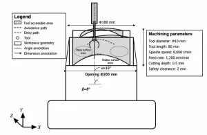
Deep-cavity geometry requires complex material removal within a restricted space. Coordinated A-axis and C-axis movements allow the tool to approach the workpiece from multiple angles.
The machining strategy progresses layer by layer from the cavity opening toward the bottom. Each layer requires dynamic adjustments to tool tilt and swivel angles.
These adjustments keep the tool under favorable cutting conditions. Tool selection combines slender ball-end mills with tapered cutters.
Slender cutters perform rough machining along the cavity depth. Tapered cutters finish sidewalls and machine chamfers.
Parameter optimization balances tool rigidity with machining stability. Lower cutting depths and higher spindle speeds reduce cutting forces and vibration.
Tool-path planning combines helical descent with radial layer-by-layer machining. This strategy prevents abrupt direction changes near the cavity bottom.
The reported application achieved IT7 machining accuracy in an engine block mold. Surface roughness remained within Ra 1.6 μm.
Machining efficiency increased by 45% compared with the conventional method. Five-axis technology therefore supports accurate and efficient machining of deep engine-mold cavities. :chatgpt-content-reference{index=”9″}
Five-axis automotive mold machining requires systematic parameter optimization and quantitative verification. Comparing three-axis and five-axis machining reveals differences across key performance indicators.
Optimization coordinates cutting speed, feed rate, tool selection, and path planning. Proper parameter combinations directly influence machining quality and production efficiency.
The evaluation therefore considers machining time, surface quality, tool life, and machining accuracy. These indicators provide a broader assessment of five-axis machining performance.
Five-axis machining showed significant improvements across the reported key indicators. Machining time decreased by more than one quarter.
Material removal rate increased by 50%, while fewer setups further shortened the production cycle. Surface roughness improved by 50%.
Machining accuracy improved by nearly 47%, while the scrap rate decreased by more than 60%. Tool vibration also declined significantly, while tool life increased by 50%.
These results indicate improved cutting stability during five-axis machining. They also provide quantitative support for automotive mold applications. :chatgpt-content-reference{index=”10″}
| Evaluation Indicator | Traditional Three-Axis Machining | Five-Axis Simultaneous Machining | Improvement |
|---|---|---|---|
| Machining Time (h) | 12.5 | 9.2 | 26.4% ↓ |
| Surface Roughness Ra (μm) | 1.8 | 0.9 | 50.0% ↓ |
| Tool Life (uses) | 180 | 270 | 50.0% ↑ |
| Machining Accuracy (μm) | ±15 | ±8 | 46.7% ↑ |
| Peak Tool Vibration (m·s⁻¹) | 3.2 | 1.7 | 46.9% ↓ |
| Material Removal Rate (cm³·min⁻¹) | 28 | 42 | 50.0% ↑ |
| Number of Setups | 3 | 1 | 66.7% ↓ |
| Scrap Rate (%) | 2.8 | 1.1 | 60.7% ↓ |
Table 1. Comparison of Five-Axis Simultaneous and Traditional Machining Process Parameters
Five-axis machining brings major process improvements to automotive mold manufacturing. Precise tool orientation control and nonlinear error compensation improve machining stability and accuracy.
Optimized RTCP functions enable smoother tool-path control, while multi-axis interpolation reduces machining errors. Collision detection also improves safety when machining complex structures.
Process verification shows improvements in machining efficiency, surface quality, and tool life. These capabilities support increasingly precise and efficient automotive mold production.
As intelligent manufacturing and Industry 4.0 advance, five-axis technology will play a larger role in automotive mold manufacturing. It will support the industry’s transition toward higher precision, efficiency, and intelligent production.