
What impact does CNC tool selection have on the CNC machining process?
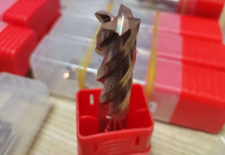

Polygonal parts are common components in the field of machining. Due to their irregular contours featuring multiple flat edges and corners, they place high demands on the rationality of milling processes and machining accuracy.
China’s high-end CNC machining equipment continues to develop toward higher precision, higher performance, and multifunctional integration.
This development drives significant changes in the technical characteristics of polygonal part machining.
Traditional machining processes often encounter vibration, thermal loads, stress concentration, and cumulative errors when machining polygonal parts.
The asymmetrical structure, thin walls, and difficult clamping of these parts cause these issues during the milling process.
These factors reduce machining accuracy and degrade surface quality.
In recent years, manufacturing scholars have carried out extensive research on the machining of polygonal parts.
They have explored effective methods to improve machining accuracy and surface quality from multiple perspectives.
These studies include process parameter optimization, toolpath optimization, surface topography simulation, and micro-mechanism analysis.
Based on practical CNC milling operations and production experience, this paper analyzes the geometric characteristics, process optimization strategies, and key considerations during part machining.
The study investigates more rational methods for evaluating surface quality.
These methods help overcome manufacturing bottlenecks and improve manufacturing quality.
They also provide effective support for strengthening China’s core competitiveness in precision manufacturing.
Common polygonal parts in machining include the following categories:
These consist of multiple planes and the edges formed by their intersections, making them relatively simple to machine.
These are characterized by combinations of multiple spatial planes or regular surfaces, with relatively fixed geometric relationships between surfaces.
Machining complexity is high, but challenges such as coordinate transformation and interference can be addressed through precise programming.
These structures contain a large number of irregular surfaces and are commonly used in the aerospace industry; machining is extremely difficult.
This paper focuses on the first two categories of polygonal parts.
Due to the highly variable toolpaths during machining, collisions are likely to occur between the tool and the machine tool, workpiece, or fixture.
Difficulties in clamping often result in the workpiece being cantilevered, leading to elastic deformation during machining and affecting machining accuracy.
As the part’s geometry continuously changes asymmetrically during machining, the overall rigidity also fluctuates.
These changes in rigidity at the tool-workpiece contact point lead to reduced machining accuracy.
Frequent changes in machining methods cause variations in heat generation during processing.
Different heat levels arise when machining flat surfaces, edges, and chamfers.
These variations create uneven residual stresses and result in deformation of polygonal parts.
Engineers analyze CAD drawings and 3D models before starting the machining process.
They first create stable and reliable large-area surfaces that act as reference planes.
They then perform all subsequent machining operations based on these established reference planes.
Engineers rationally design the milling sequence.
They perform comprehensive and efficient rough machining first to secure sufficient material allowance for later finishing.
They then carry out precision machining to achieve the final dimensional and surface requirements.
During the initial clamping and whenever clamping positions must be changed, ensure the workpiece is in the most rigid state.
Clamping fixtures must be designed so that they do not interfere with machining paths.
Engineers reduce the number of clamping operations whenever possible.
During each clamping stage, they complete as many feature machining operations as possible.
If the workpiece is a thin-walled part, design specialized internal support fixtures to ensure machining rigidity.
Multi-clamping machining operations require the use of consistent setup conditions across different stages.
Engineers establish a unified measurement reference across all clamping configurations.
This reference ensures accurate coordinate system transformations between each clamping operation.
At the same time, clamping and positioning accuracy must be achieved using precision vices, precision-fit fixtures, or similar methods.
When fixtures cannot establish a unified coordinate transformation reference, engineers rely on machine tool probes for measurement.
They use the probe to collect positional data from the workpiece.
Based on this data, they establish a new coordinate system to maintain a consistent reference framework.
During rough machining, cycloidal milling and dynamic high-speed milling strategies can be employed to replace traditional reciprocating paths with cycloidal paths.
This reduces high-speed loads while improving cutting efficiency and effectively controlling residual stress.
When rough machining large parts or significantly asymmetrical parts, the workpiece should be divided into multiple machining zones.
A symmetrical alternating machining approach should be adopted to balance and offset the effects of machining thermal deformation.
Adaptive machining should be prioritized for finishing.
The tool automatically adjusts the machining spacing based on the surface and curvature, ensuring a constant material height between adjacent toolpaths.
This prevents variations in machining accuracy across different areas.
For machining side walls or steep surfaces, switch to contour machining to improve machining efficiency.
When machining corners and fillet transitions, ensure that the tool automatically reduces speed to minimize tool impact.
Engineers complete the main body machining of a polygonal part during the finishing stage first.
They then use small-diameter tools, such as ball-nose cutters, to clean up the root fillets.
They also optimize the machining program to prevent tool change marks on the surface.
Surface roughness and waviness are two key parameters of surface topography.
Surface roughness primarily reflects the average deviation of the actual machining amount from the ideal value within a given sampling length;
Low-frequency vibrations, machine tool geometric errors, and spindle rotational errors occur during the machining process.
These factors generate variations between peaks and valleys at the microscopic level.
Waviness reflects this type of surface variation on the machined part.
Both are important factors in evaluating surface quality.
Physical and mechanical properties primarily encompass the following two aspects:
Residual stress refers to internal stress that remains on the surface of a part after machining.
This stress becomes one of the main causes of cracks in polygonal parts during subsequent use.
Meanwhile, the machining process produces a work-hardened layer due to plastic deformation and high temperatures.
This layer induces phase transformations and increases surface hardness in polygonal parts, which makes them more prone to fatigue failure in later applications.
Cutting speed refers to the rotational speed of the cutting tool.
Engineers increase the cutting speed within an appropriate range during machining.
This adjustment reduces cutting forces and suppresses the formation of built-up edges.
As a result, the surface finish of multi-sided parts improves to a certain extent.
However, it also leads to higher cutting temperatures, which generate more residual stresses and cause surface hardening.
This is the key parameter determining the speed of a single tool movement.
Excessive feed rate will degrade surface finish quality, while an insufficient feed rate will reduce machining efficiency.
Depth of cut directly affects cutting forces and heat generation;
It is the parameter representing the vertical distance the milling cutter travels.
Excessive depth of cut increases cutting forces and heat accumulation, causing surface deformation in multi-sided parts and reducing surface finish quality.
Manufacturers control the precision and consistency of the arc radius at the cutting edge and the edge rounding radius of a milling cutter.
These geometric characteristics directly influence cutting sharpness during machining.
They also determine the amount of remaining material allowance on the workpiece.
Low precision leads to machining errors and can easily cause periodic vibration marks.
The cutting tool system must have good dynamic balance parameters.
Imbalance can cause forced vibrations in high-speed rotating tools, resulting in noticeable vibration marks during machining and compromising surface quality.
Failure to replace worn tools in a timely manner can also lead to a deterioration in the surface roughness of polygonal parts due to increased cutting forces and rising temperatures.
The primary influence of material properties stems from material uniformity.
Impurities and compositional segregation in metal raw materials, castings, or forgings create material inconsistencies.
These inconsistencies cause variations in milling resistance and chip formation at different locations.
As a result, surface finish quality varies across the machined part.
Additionally, the heat treatment conditions of metal parts—including hardness, strength, and ductility—directly affect the surface finish quality of multi-sided parts.
The rigidity and thermal stability of the machine tool also have a certain impact on machining quality.
Insufficient rigidity in the system generates machining vibrations during operation.
Poor thermal stability causes thermal deformation in key components such as the spindle and ball screws.
Both factors reduce machining accuracy and negatively impact the final machining quality.
Furthermore, the response efficiency and precision of the machine tool’s servo system, as well as the accuracy of error compensation, all affect the machining quality of complex contours or surfaces.
Given the inherently complex structure of polygonal parts, minimizing the impact of vibration is particularly critical.
The first step should be to inspect the milling machine, optimize the tooling system, and repair worn transmission components.
Engineers design and implement damping and vibration-suppression devices, such as damping tool holders and vibration-suppressing fixtures.
These measures help reduce vibration during the machining process.
When machining various surfaces, ensure that the radial and axial engagement of the tool change gradually.
Techniques such as cycloidal grooving and dynamic milling should be employed to avoid excessive full-radial cuts and right-angle turns.
Additionally, use arc-entry milling; when transitioning between surfaces on polygonal parts, reasonably design the post-lift path and the starting point for the next surface.
Machining polygonal parts produces a complex stress distribution across the workpiece.
For metal parts with low rigidity, engineers design auxiliary supports at structurally weak areas.
They also apply six-degree-of-freedom constraints to ensure stable positioning during the machining process.
For parts prone to deformation, sequential loading or multi-point distributed clamping should be adopted to avoid stress concentration.
Engineers prioritize efficiency during the rough machining process for multi-sided parts.
They fully utilize the machine tool’s maximum power and the tool’s strength to remove stock rapidly using large cutting depths and high feed rates.
After rough machining, they perform semi-finishing operations to correct the geometric shape.
The finishing process should prioritize quality, employing small cutting depths, low feed rates, and high spindle speeds to reduce cutting forces and heat generation.
The coordination of these processes achieves a balance between quality and efficiency.
Conduct simulation machining using 3D models to optimize cutting parameters.
Implement differentiated parameter designs based on feature importance and structural rigidity to ensure more appropriate cutting parameters are applied to different areas during mass production.
Design is tailored to material properties.
For hard-to-machine materials with high hardness, high-pressure cooling technology can be selected during finishing, and atomized lubricant spray significantly improves surface quality.
During general machining, coolant is sprayed directly and thoroughly onto the contact zone between the tool tip and the chips to reduce ineffective flushing.
Engineers combine simulation analysis of clamping errors and deformation with real measurements collected during production.
They use this integrated data to apply program offset compensation during the finishing stage.
A unified reference system ensures consistent correction throughout the process.
This approach better accommodates the frequently changing features of multi-sided parts and reduces the impact of machining errors.
On one hand, maintenance is performed to reduce the impact of vibrations generated during the production process, thereby lowering the probability of vibration marks.
Additionally, an extremely small radial depth of cut is applied during the final pass of finishing to smooth out microscopic vibration marks left by previous cuts effectively.
On the other hand, overlapping toolpath technology is employed, with adjacent toolpaths overlapping by approximately 30% to 50% to minimize the formation of tool change marks.
Sensors are used to monitor machining quality precisely; the system issues timely alerts for abnormal vibrations, temperatures, and other issues and automatically shuts down to prevent widespread quality defects.
Adaptive control technology works together with the machining system to adjust the feed rate in real time.
The system fine-tunes the feed rate based on feedback from force or vibration signals.
This optimization improves cutting conditions across different surfaces and edges, reduces flutter, and enhances the manufacturing quality of multi-sided parts.
The evaluation is performed using the two-dimensional profilometry method, in which a stylus is moved along a selected reference line across the surface being measured.
Following ISO 4287 standards, engineers record the profile curve during surface measurement.
They then analyze the recorded data to determine key surface parameters, including the arithmetic mean deviation (Ra), mean width of contour elements (Rsm), contour skewness (Rsk), and contour kurtosis (Rku).
Engineers measure each reference surface at least three times and then calculate the average value from the results.
The results are compared against the company’s internal control standards; for example, Ra ≤ 1.6 μm.
If the measured values exceed the specified range, the surface quality is deemed non-conforming.
Engineers use a white-light interferometer and a confocal laser scanning microscope to capture the three-dimensional surface topography.
They then calculate key parameters such as arithmetic mean height (Sa), root-mean-square height (Sq), and maximum height (Sz) from the obtained data.
Combined with the dominant texture direction and contact surface wetting characteristics, these results are compared with the company’s internal control standards to evaluate surface quality.
For example, a standard may require Sa ≤ 0.5 μm and a consistent dominant texture direction.
When measured results fail to meet these requirements, engineers adjust the manufacturing process according to the actual data obtained.
For complex multi-sided parts with stringent fit requirements, evaluation can be conducted by establishing a surface quality scoring system.
Engineers configure the evaluation system according to the actual assembly requirements of the workpiece.
They assign different weights to parameters such as Ra, Rz, Sa, Sq, RSm, Sdr, and Rku based on their importance.
At the same time, they exclude parameters that are not relevant to the evaluation process.
For example, Ra may account for 50%, Sa for 20%, Sm for 20%, and Rku for 10%.
Scores are calculated based on these standard values, and a minimum passing score is established;
Parts with a total score below this threshold are deemed non-conforming.
Polygonal parts are complex and high-precision mechanical components.
Their manufacturing processes require strict control over machining paths, machine tool performance, clamping quality, supporting programs, and intelligent control systems.
Scientific design of machining paths and rational evaluation of machining quality are key to ensuring precision machining and promoting quality improvement.
During actual production, manufacturers encounter multi-sided parts with diverse structures and complex details.
Engineers should combine process planning with adaptive machining technology according to specific production conditions.
Efforts should be made to minimize errors caused by vibration and thermal deformation as much as possible.
Manufacturers should also upgrade machining systems by integrating intelligent sensing and monitoring technologies.
These technologies can track and evaluate surface machining quality in real time.
The system can then automatically and rationally adjust machining plans during production.
This approach promotes the development of multi-sided component manufacturing toward higher intelligence, greater precision, and stronger integration.
With the rapid development of CNC machining technology, CNC tooling…
Confused about 5-axis machining vs 3-axis and 3+2-axis? This guide…
This article systematically analyzes common machining surface defects including surface…