How to efficiently machine shaped parts on CNC mill-turn machines?


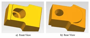
As one of the core components of mining crushers, the CS D P01-05 cutting teeth require machining of a long, oval-shaped deep hole (approximately 150 mm deep) at one end, which is inclined at a 15° angle;
This process represents a critical bottleneck affecting production efficiency and part delivery. Previously, a small vertical machining center was used for machining.
We face several constraints in practice. These include limited spindle power, insufficient torque, and long cutting tools with low rigidity.
These drawbacks trigger violent tool chatter and frequent tool failure in machining. The outcome is low production efficiency, high machining costs and long lead times.
A single batch of roughly 100 workpieces takes 45 to 50 days on one CNC machine. The machine runs a two-shift schedule for 16 hours each day.
This long cycle creates serious delays to production plans. We therefore see great practical value in exploring CNC machining methods for inclined oblong deep holes.
Many researchers have carried out related extensive studies for this purpose.
Some experts built mathematical models for complex surfaces, and optimized toolpath planning and deployed adaptive feed rate algorithms. Also tuned high-speed cutting parameters through experiments.
These steps lifted both machining accuracy and efficiency at the same time. Our study follows this technical route and obtains similar positive outcomes.
Another expert focused on tool management and accuracy control in CNC machining and put forward practical measures to make full use of cutting tools.
His solutions cover tool grinding inspection, real-time tool monitoring, and standardized tool management.
They developed a self-adaptive toolpath optimization method for five-axis CNC machining.
This method effectively optimizes toolpaths, reducing the maximum geometric deviation from 70 μm to 35 μm—a 50% reduction.
Some professors, through an analysis of CNC milling process issues, proposed optimization strategies for the CNC milling of mold components.
Research results show that optimization reduced machining time by 17% and effectively improved part machining quality.
The method boosted production efficiency noticeably.
Five-axis Machining and Multi-axis Toolpath Research
Someone researched optimization technology for 5-axis tool paths and combined optimization theory with intelligent algorithms. His work offers an effective optimization route for 5-axis machining of complex curved surfaces.
They ran post-processing calculations. These calculations convert 3-axis tool path files into usable 5-axis CNC codes.
They verified the reliability of these codes via software simulation.
The model shortens tool-switching time between machining zones and increases milling productivity.
They presented a method for determining the optimal cutting diameter and machining width for interference surfaces.
Under interference constraints, their algorithm selects proper tool diameter and cutting width. It shortens machining time and improves efficiency for CNC machining of complex surfaces.
Other researchers merged data-driven models with physical machining limits. They formed an optimization strategy for milling parameters on complex surfaces. This strategy improves the machining quality of inserts and drops the scrap rate by 5.25%.
These measures successfully improved both quality and efficiency for thin-walled titanium alloy frame parts.
We systematically analyze the machining requirements of the part and the performance parameters of the available equipment.
This paper proposes switching to a CNC contouring milling machine. It also optimizes cutter selection and cutting parameters at the same time.
We compare machining efficiency, production costs and process sequences before and after the upgrades. The comparison validates that the revised process is feasible and economically beneficial.
These findings offer theoretical guidance and practical references for process optimization of similar deep-hole components.
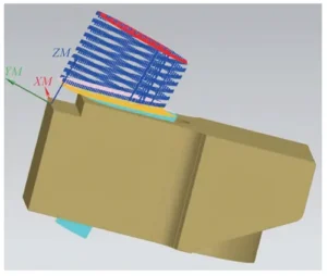
The oblique, oblong deep holes in the CSDP01-05 cutting teeth shown in Figure 1 were originally machined on a small vertical machining center.
The spindle motor carries a low-rated power. Its belt drive structure delivers limited output torque. This setup fails to supply enough torque and power for high-efficiency cutting under large cutting depths.
Space restrictions apply when machining these inclined oblong deep holes. We cannot use an overly large-diameter cutter. We therefore choose a φ32 mm square-shoulder end mill with an R0.8 mm corner radius.
The tool overhang reaches 160 mm. Its length-to-diameter ratio equals 5. Steel milling cutter shanks normally require a length-to-diameter ratio no higher than 3 for stable cutting.
This constitutes a deep milling operation, resulting in severe tool rigidity deficiency.
During machining, significant tool chatter occurs, leading to numerous adverse issues such as severe tool damage and short tool life.
To reduce tool vibration during machining and extend tool life, the only viable strategy is to use a machining approach with a small cutting depth and high feed rate, with a cutting depth per pass of only 0.5 mm.
With an effective machining depth of 148.5 mm, the operator must complete the cutting in 297 layers.
Furthermore, to suppress tool chatter during machining, the feed rate must be kept at a low level, resulting in low machining efficiency.
The toolpath and number of layers are shown in Figure 2.
Machining a single workpiece with a slanted, oblong deep hole takes up to 7 hours. With each work shift lasting 8 hours, a single machine can process only one part.
For a batch of 100 parts, it would take 45 to 50 days to complete using a single machining center operating on a two-shift schedule, severely impacting production progress and efficiency.
In addition, tool wear costs are excessively high, and severe tool chatter occurs during machining.
We must replace the cutting edges of the inserts at least four times for each part (two inserts).
With a unit price of 106 yuan per insert, the machining cost per part reaches as high as 212 yuan, and tooling expenses now far exceed a reasonable range.
We adopt a complex process flow. Before machining on a small vertical machining center, we perform two extra auxiliary processes: marking hole positions and pre-drilling φ50 mm pilot holes using a radial drill.
This increases the time required for other processes and inter-process transfers, while also raising quality risks due to potential human error.
The design concept behind the improved plan is as follows:
Use a high-power CNC milling machine equipped with a gear-driven speed change system and adopt a cutting strategy of “large cutting depth + few depth layers + small feed (small radial cutting width)” to replace the original cutting strategy of “small cutting depth + many depth layers + large feed rate” used on a small vertical machining center.
At the same time, a φ40 mm welded carbide milling cutter with an increased diameter is used.
This approach leverages the machine tool’s high power and high torque, as well as the tool’s high rigidity, while utilizing cutting fluid for adequate cooling and lubrication.
The machining process involves milling to a depth of 148.5 mm in three layers, with the peripheral machining allowance milled in five passes.
We reduced the total number of cutting layers substantially from the initial 297 to 15, cutting the layer count by 94.9% and greatly boosting machining efficiency.
The use of a larger-diameter tool and a small feed rate reduced cutting vibrations and minimized tool wear.
Additionally, because the new machine tool employs a gear-driven transmission system with high output torque, it is capable of directly drilling a φ50 mm pilot hole.
We further shortened the machining cycle by consolidating processes and removing the marking and pilot hole drilling steps.
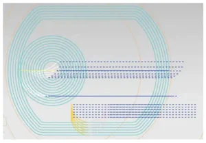
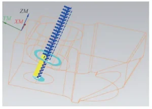
The static wireframe front view and isometric view of the improved toolpath are shown in Figures 3 and 4, respectively.
Based on an analysis of the technical requirements for part machining, this deep, oblong, tapered hole serves as an anti-rotation hole for bolts.
The part does not demand tight, high-precision tolerances. We give priority to high-power, high-rigidity, high-torque equipment instead of small vertical machining centers.
This choice avoids the drawbacks of small vertical machining centers. These weaknesses include insufficient power, limited rigidity and low output torque.
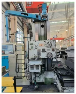
There are currently two simple FK100 CNC copy milling machines (see Figure 5). Although their accuracy is slightly lower than that of small vertical machining centers, they can meet the part machining requirements.
These machines have a rated spindle power of 25 kW. They adopt a gear-shift transmission system. They can provide a peak output torque of 550 N·m. Their overall structural rigidity performs well.
The machines support deep-cut machining tasks. For this reason, they work as suitable replacement equipment.
Figure 6 shows a machining validation test conducted using a CNC copy milling machine and a custom-built fixture.
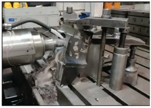
This scheme replaces the machining equipment with an FK100 CNC contouring milling machine. It adopts a φ40 mm welded carbide 4-flute milling cutter with shallow spiral flutes.
Increasing the diameter of the shank core boosts rigidity, delivering a rigidity improvement of more than 40% compared with the original φ32 mm square-shoulder milling cutter.
The cutting section is made of welded solid carbide, offering high wear resistance and the ability to withstand cutting loads at large cutting depths.
Furthermore, with a unit price of only 302 yuan per tool, the procurement cost is low, providing excellent value for money.
A deep, oblique, oblong hole 150 mm deep was machined in three passes along the depth direction (50 mm per pass).
A transverse layered cutting strategy was employed in the circumferential direction for each depth layer, gradually removing the stock through five single-sided cuts (1.2–1.3 mm per cut) to avoid excessive tool load caused by overly large single-cut depths.
The total number of cutting layers was significantly reduced from 297 to 15, improving machining efficiency.
At the same time, the feed rate was reduced from 15,000 mm/min to 40 mm/min, which reduced tool vibration during cutting and extended tool life.
During the machining process, high-pressure internal-cooling cutting fluid (5% concentration, 0.8 MPa pressure) is continuously applied.
On the one hand, this rapidly reduces the temperature in the cutting zone (keeping it below 200°C), thereby minimizing thermal wear on the cutting tool;
On the other hand, the formation of a lubricating film improves friction conditions at the cutting interface, reducing cutting resistance by more than 30% and suppressing tool chatter.
Because the new machine tool has high power and high torque, it can directly drill a φ50mm pilot hole.
As a result, the original marking and pilot hole drilling processes using a radial drill have been eliminated.
We carry out the revised process on the FK100 CNC contouring milling machine. We simplify the workflow into two steps: pilot hole drilling, followed by milling the elongated deep hole.
Workers finish multiple machining tasks within one clamping. This change cuts the number of workpiece transfers between processes.
Post-processing was performed on the improved programs; some of the programs are shown below.
After the process improvements, the use of a φ40 mm brazed carbide milling cutter significantly reduced chattering during machining.
Furthermore, the number of cutting passes was drastically reduced;
Combined with small feed rates and effective cooling and lubrication, this led to a significant decrease in tool wear rates and tool costs.
Before the improvement, machining a single part consumed 2–3 φ32 mm square-shoulder milling inserts (106 yuan/insert), resulting in a tool cost of approximately 212 yuan per part (calculated based on 2 inserts);
After the improvement, each tool can machine 3–5 workpieces, with a per-piece tool cost of approximately 75 yuan (calculated based on 4 workpieces per tool).
This results in a savings of 137 yuan per workpiece on tool costs, a 64.6% reduction in tool costs, and a total savings of 13,700 yuan on tool costs for a batch of 100 workpieces.
After improving the original machining method, it was implemented in actual production and validated.
Through the optimization of machining equipment and process parameters, the machining efficiency for deep, oblique, oval holes in the CSDP01-05 cutting teeth was significantly improved.
Following the improvements, the machining time per part was reduced from 7 hours to 2.5 hours, a 64.3% reduction;
Operators finish 3 parts within an 8-hour shift. The previous shift output was only 1 part. This change raises per-shift output by 200%. The batch cycle for 100 parts shrinks from 45–50 days to 13–15 days.
We cut the batch production cycle by roughly 70%. The overall production efficiency improves by around 280%. The average processing time saved per batch of 100 parts was 35 days.
Two 8-hour daily shifts are arranged in the workshop. The branch factory sets the hourly labor cost at 60.9 yuan.
The optimized process reduces the total working hours by 560. It brings down labor expenditure by 34,000 yuan and tooling outlay by 13,700 yuan.
Together, these adjustments yield a total cost saving of 47,700 yuan.
Following process improvements, two auxiliary steps—marking and pre-drilling pilot holes with a radial drill—were eliminated.
This saved 10 minutes per part in marking time and reduced process turnaround time by 15 minutes per part.
At the same time, it lowered the risk of dimensional deviations caused by human error, and the first-pass yield rate increased from 99.2% to 99.8%.
Furthermore, the high rigidity of the CNC contouring milling machine and the cutting tools has significantly reduced tool chatter during machining.
We drastically reduce the total number of tool paths. A reasonable nominal cutting thickness is assigned to each circumferential layer.
The process also makes full use of cooling and lubrication supplied by cutting fluid.
These improvements significantly boost production efficiency.
They extend tool service life. The machining process gains higher safety and stability accordingly.
This improved process has been validated through batch machining of three production runs totaling 321 parts.
The machining process maintains stable and reliable operation. Finished parts hold consistent dimensional accuracy. Operators control dimensional deviations within ±0.1 mm. This technology has matured enough for broad industrial adoption.
The method targets a specific scope of workpieces. It is primarily applicable to medium- and low-precision deep-hole components of medium and low carbon steel.
These parts carry a tolerance grade of IT10 or below and feature an aspect ratio (length-to-diameter) above 3.
High-rigidity equipment forms the hardware foundation. We refine machining strategies and cutting parameters.
Proper cutting tools are selected to match the processing requirements. These actions balance machining efficiency and production cost simultaneously.
To guarantee operational safety, we implement a layered cutting strategy with ample cutting fluid cooling. This setup limits cutting loads and cutting temperatures effectively.
The scheme strongly inhibits severe machining chatter. It also greatly reduces the probability of tool breakage.
This fully complies with national safety standards and ensures reliable safety performance.
This work addresses the technical bottlenecks encountered during deep-hole machining of oblique-toothed oblong holes using CSDP01-05 cutters.
The present study proposes a process improvement solution based on a CNC contouring milling machine.
We select better-matched equipment and upgrade cutting tools. Process workflows and cutting parameters receive careful calibration. We combine and restructure separate machining operations.
The revised scheme delivers substantial gains in machining efficiency. It achieves notable cost-control performance. It also enhances the consistency and stability of machined outcomes.
Future researchers can apply the response surface method for further parameter optimization. They may validate high-efficiency machining solutions with advanced cutters and CNC systems.
We can also adapt this process for deep-hole machining of difficult-to-cut materials. Stainless steel and cast iron are promising candidate materials. This expansion will broaden the application scope of the developed technology.