How to efficiently machine shaped parts on CNC mill-turn machines?



Thin-walled cylindrical shell components are widely used in high-tech manufacturing sectors such as aerospace due to their sealing properties, lightweight design, and high strength.
Common structural requirements for thin-walled cylindrical shells include lightweight construction and high strength.
The surfaces of these components often feature complex geometries, such as various patterns or grooves, which make machining difficult and require extremely high precision.
Due to their thin walls, low rigidity, and susceptibility to vibration, they are prone to irregular deformation during machining.
Engineers design internal support fixtures for clamping to minimize deformation and enhance the part’s rigidity and structural integrity.
They use ANSYS to perform finite element analysis on the internal support fixtures to verify the feasibility and effectiveness of the design.
The use of these fixtures significantly improves machining accuracy and production efficiency while reducing manufacturing costs, and provides a reference for the machining of similar products.
This holds practical application value in the aerospace sector and makes a positive contribution to advancing manufacturing technology.
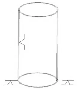
Engineers define the ideal shape for a thin-walled cylindrical shell part as a straight-walled thin-walled cylindrical shell (Fig. 1).
They manufacture this part from 7075 aerospace-grade aluminum, giving it an outer diameter of 208 mm, an inner diameter of 200 mm, a height of 400 mm, and a wall thickness of 0.3 mm after rough machining.

Engineers reduce weight effectively while ensuring the strength requirements of the thinned areas.
They machine the outer surface of the thin-walled cylindrical shell to meet specifications.
The machining process requires milling on the exterior of the thin-walled cylindrical shell component, so engineers employ an internal support clamping method.
They also adopt a clamping method to counteract the effects of the component’s own weight during machining.
Engineers set the fixture positioning references to the bottom surface and the inner surface due to the special machining requirements of thin-walled cylindrical shell parts.
The bottom surface and inner surface of thin-walled cylindrical shell parts undergo machining, so they exhibit random variations that engineers find difficult to predict accurately.
Therefore, it is necessary to assume that the bottom surface and inner surface have theoretical shapes and to design a segmented internal support fixture based on these positioning references.
Based on the structural characteristics of thin-walled cylindrical shell parts and the requirements for ensuring machining accuracy, this study designed an automatic, uniformly distributed internal support fixture.
Analysis shows that, compared to pneumatic fixtures, hydraulic fixtures offer superior performance in key areas such as force, rigidity, precision, and stability, making them particularly suitable for machining scenarios that demand high load capacity, high precision, and high stability.
High-end manufacturing sectors (such as automotive and aerospace) frequently rely on hydraulic clamping systems.
This fixture employs a hydraulic pressure-holding design, with hydraulic lines and valves integrated into the fixture body for enhanced convenience.
Hydraulic pressure-maintaining, indexing-block, internal-support clamping fixtures are equipped with multiple sets of auxiliary supports.
These fixtures use hydraulic oil as the driving fluid, which significantly reduces vibration during clamping and unloading, thereby minimizing deformation of the workpiece.
In addition, these hydraulic clamping fixtures with indexing-block internal-support mechanisms offer excellent versatility and can accommodate thin-walled tubes of various sizes.
High-Precision Positioning: Ensures that the inner bore of the workpiece (typically thin-walled sleeves or ring-shaped parts) is concentric with the machine tool spindle, thereby guaranteeing post-machining geometric tolerances such as coaxiality between inner and outer circles and end face runout.
Uniform Clamping Force: Provides circumferentially uniform clamping force through the even radial expansion of the six-lobed support plates, effectively preventing deformation of thin-walled workpieces.
Automation and Pressure Maintenance: Hydraulic drive is employed to achieve rapid automatic clamping and release.
The pressure maintenance system ensures that clamping force remains constant throughout the machining process, even if the hydraulic power unit stops operating, providing a safe and reliable solution.
High Rigidity and Stability: The fixture body and support plates must possess sufficient rigidity and wear resistance to withstand cutting forces, ensuring process stability and workpiece surface quality.
Given that different models of storage tanks incorporate thin-walled cylindrical shell components, this study thoroughly considered their machining processes and inherent characteristics to design a block-divided internal support fixture.
Since the thin-walled cylindrical shell components are positioned and used vertically, the fixture was designed for vertical use.
Based on the characteristics of the parts, the positioning method shown in Figure 2 was adopted.
When mounted vertically on the machine tool table, the lower section functions as a large flat surface, providing both positioning and clamping.
The positioning method follows the “one face, one pin” principle.
The positioning reference for the thin-walled cylindrical shell parts is shown in Figure 2, with the lower end face and inner wall serving as the fixture’s reference surfaces.
During operation, driven by hydraulic pressure, the six-lobed support blocks move outward simultaneously and uniformly to clamp the inner wall of the thin-walled cylindrical shell.
Conversely, driven by hydraulic pressure, the six-lobed support blocks move inward simultaneously and uniformly to release the inner wall of the thin-walled cylindrical shell.
The hydraulic pressure-holding automatic internal support fixture employs an internal support expansion mechanism.
Its structure is simple; the oil circuit on/off and fluid flow direction are controlled via valve buttons.
It clamps parts stably and uniformly without pressure leakage, ensuring pressure drop and achieving pressure-holding functionality.
Even if the oil circuit fails, internal support is still maintained, effectively improving clamping reliability.
It can also convert a relatively small driving force into a larger support force, achieving uniform internal support for the hydraulic pressure-holding automatic internal support fixture.
The small gap between two adjacent internal expansion sleeves provides a large clamping area, thereby enhancing the rigidity of the machining zone.
The specific structure of the hydraulic pressure-maintaining automatic internal expansion fixture is shown in Figure 3.
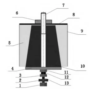
How it works: Pressing the button activates the hydraulic pump to deliver oil.
The flow rate is controlled by an adjustable reducer to regulate the speed of the hydraulic fluid, which drives the clutch.
The clutch, in turn, actuates the directional control valve to control forward or reverse movement, causing the rotary table to move up or down.
This action drives the six sliding plates to move up or down, which in turn pushes the six inner expansion sleeves inward or outward.
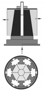
When the inner expansion sleeves (6 pieces) move outward, they clamp the workpiece against the inner wall.
The diameter of the inner expansion sleeves ranges from ⌀195 mm to ⌀205 mm, completing the clamping process as shown in Figure 4.
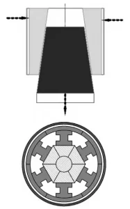
The system releases the workpiece as shown in Figure 5. The fixture then completes the unloading motion.
During unloading, the diameter of the inner expansion sleeves ranges from ⌀170 mm to ⌀190 mm.
Expansion is a critical design factor and must comply with the tolerance range of the workpiece’s bore.
The calculation of radial expansion is shown in Equation (1).
ΔR ≈ ΔL × tan(α) (1)
Where: ΔL is the axial stroke of the piston; α is the half-cone angle of the drive cone surface.
Designers calculate the minimum diameter when the support plate contracts.
They also calculate the maximum diameter when the support plate expands based on the minimum and maximum diameters of the workpiece’s inner bore.
Then they determine ΔL and α accordingly.
The clamping force must be sufficient to overcome the cutting force, but it must not be so great as to cause deformation of thin-walled workpieces.
The calculation process for the theoretical output force is shown in Equation (2).
Fradial ≈ (P × Apiston) / tan(α) × η (2)
Where: P is the operating pressure of the hydraulic system;
A (piston) is the effective working area of the piston.
Engineers determine the actual clamping force required through mechanical simulation or empirical calculation based on the cutting process.
To ensure reliable pressure retention, the cone angle must satisfy the self-locking conditions, as shown in Equation (3).
α < arctan(μ) (3)
Where: μ is the coefficient of friction (for steel-on-steel with lubrication, approximately 0.1 to 0.15).
Engineers typically design α between 5° and 8° to ensure that the joint will not loosen even in the event of hydraulic failure.
Designers incorporate precision guide slots, such as dovetail slots, into the fixture base to ensure that the six-lobed plates move radially in unison without any wobble.
To validate the research findings and demonstrate their practical value, this study conducted a finite element stress analysis of the clamping of thin-walled cylindrical shell components for storage tanks using a hydraulic pressure-maintaining automatic internal bracing fixture.
By subjecting the interior of the thin-walled cylindrical shell components to varying bracing forces, the analysis examined external changes and deformation patterns to verify the theoretical soundness and reliability of the approach.
Establishment of Clamping Forces in FEA: Taking the thin-walled cylindrical shell component as the subject of study, the aim is to determine the minimum clamping error and the most suitable clamping force for the shell component and to verify their accuracy.
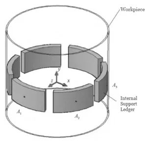
The model assumes support points A1, A2, A3, A4, A5, and A6 for the internal support clamping of the thin-walled cylindrical shell component, and these points define the centers of the contact surfaces with the workpiece.
The outer diameter of the thin-walled cylindrical shell component is ⌀210 mm, the wall thickness t is 5 mm, the height L is 400 mm, and the material is aerospace-grade aluminum 7075-T651.
The elastic modulus E is 71 GPa, Poisson’s ratio ν is 0.32, and the yield strength σs1 is 503 MPa.
The outer contour and the inner contour of the workpiece follow the same curve, featuring 6 petals uniformly distributed on the inner wall of the workpiece.
Each petal has a central angle of 0° and a length of 30 mm.
To verify the accuracy of clamping errors, the study applied different clamping forces to the part.
Engineers use finite element ANSYS simulation analysis to obtain the deformation contour map of the workpiece.
The analysis considered the increase in internal support force (neglecting the displacement of the workpiece and its own elasticity).
The hydraulic pressure-holding automatic internal support fixture applies internal support forces of 2000 N, 5000 N, 8000 N, and 10,000 N through its support force system.
The thin-walled cylindrical shell part then exhibits deformation under each applied force level.
Figures 7 through 10 present the corresponding deformation results.
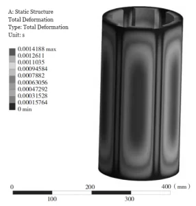
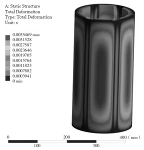
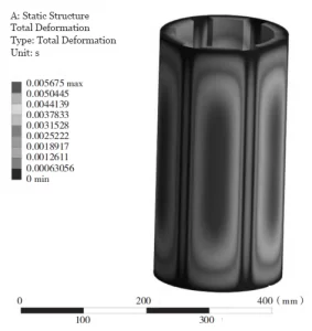
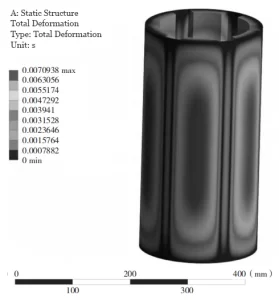
The deformation of thin-walled cylindrical shell parts under different internal support forces was observed; the deformation increased as the internal support force increased.
Table 1 shows a comparison of the clamping error ranges obtained for the model under internal support forces with the simulation results.
| Clamping Force (N) | Finite Element Simulation Result (mm) | Numerical Calculation Result (mm) | Error (%) |
|---|---|---|---|
| 2000 | 0.0014188 | 0.0012107 | 14.7 |
| 5000 | 0.0035469 | 0.0034493 | 2.75 |
| 8000 | 0.0056750 | 0.0055950 | 1.41 |
| 10000 | 0.0070938 | 0.0070328 | 0.86 |
Table 1. Comparison Between Numerical Calculation of Clamping Error and Finite Element Simulation Results
As shown in Table 1, the theoretically calculated clamping error is close to the results of the finite element simulation analysis.
The error increases as the internal support force increases, but when the force reaches a certain value, the error remains relatively constant.
This fully validates the accuracy of the established clamping force.
This study designed a segmented internal support fixture for thin-walled cylindrical shell parts used in storage tanks, specifically a hydraulic pressure-maintaining automatic internal support fixture.
A finite element analysis was conducted on the internal support force applied by the fixture.
The results showed that as the internal support force increased, the clamping force also increased, and the deformation of the thin-walled cylindrical shell parts became greater; however, these values were close to the theoretical calculations, indicating that the error margins were within acceptable limits.
Engineers replace the traditional external clamping method with an internal support approach.
The system then supports the thin-walled inner cavity uniformly through radial expansion.
This process shortens the overall clamping time.
Optimizing the fixture reduces clamping and positioning time, resulting in an efficiency improvement of over 300% compared to traditional methods.
This reduces tool change and adjustment times, stabilizes clamping to minimize vibration, and leads to reduced tool wear and lower tool change frequency.
Integrating the fixture with automated systems accelerates the digital transformation of the manufacturing industry.
Simplified clamping operations reduce the need for manual measurement and machining compensation, minimize machining vibrations and deformation, and ensure uniform clamping force to prevent deformation of thin-walled workpieces, thereby significantly improving machining quality.
The core objective of this research is to achieve high-precision, high-efficiency, and highly reliable internal bore positioning and clamping for cylindrical and sleeve-type workpieces (particularly thin-walled, easily deformable parts).
The hydraulic pressure-holding automatic internal support fixture is not only a powerful, specific tooling solution but also a benchmark design that embodies the modern manufacturing philosophy of precision, automation, and reliability.
In high-end manufacturing, advanced fixture design is as important as machine tool equipment and is a key factor in improving product quality and production efficiency.
This design approach provides a reference for the design of fixtures for similar thin-walled shell parts.
The core of CNC machining fixtures for thin-walled cylindrical shells lies in addressing deformation issues through structural optimization and intelligent control.
Economic benefits appear through improved efficiency, reduced costs, and fewer defects.
Social benefits emerge through technological progress, improved working conditions, and the advancement of green manufacturing.
In future applications, engineers can integrate sensors into these fixtures to enable real-time monitoring of clamping force and deformation, allowing the system to operate intelligently.

