How to efficiently machine shaped parts on CNC mill-turn machines?



Due to the high cost of four-axis and five-axis machining centers, most mold manufacturers currently use three-axis machining centers.
For standard mold components, a single setup is typically sufficient to produce a workpiece that meets specifications.
For mold components requiring machining on multiple sides, if a single setup is insufficient, multiple setups are necessary to machine from different angles to produce a qualified workpiece.
Before programming a workpiece requiring multiple setups, the process first analyzes the 3D model to determine the machining sequence for different sides.
Then, the process establishes a reference point and positions each setup relative to the same reference point to minimize machining errors.
Taking a mold slider as an example, this slider has a relatively complex structure and requires three setups and machining operations.
Based on the slider’s structure, the core is machined first, followed by the bottom surface, and finally the top surface.
The programming process is described below.
The slider features a monolithic design, meaning the slider base and the slider core are integrated into a single unit, with dimensions of 154 mm × 102 mm × 75 mm.
The slider has two independent cores spaced 20 mm apart.
The smaller core measures 13 mm × 10 mm × 41 mm, and the larger core measures 69 mm × 49 mm × 73 mm, as shown in Figure 1.
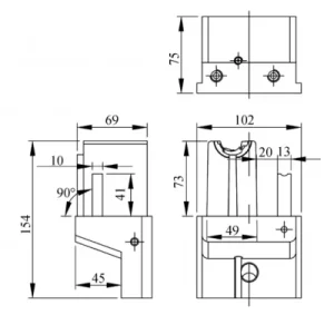
The end faces of both the large and small cores each have one curved surface, and the side of the large core features a protruding strip, requiring it to be positioned sideways for machining.
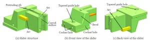
The end face of the large core—which serves as the cavity—features a non-circular curved surface and multiple small ribs, as shown in Figure 2(a).
The front and bottom surfaces of the slider are shown in Figures 2(b) and (c), respectively.
The slider seat includes an inclined surface for clamping the slider, as well as markings, water passages, and inclined guide pillar holes.
In accordance with the accuracy requirements for plastic molds, machining errors must not exceed ±0.02 mm.
The line contour and flatness of the mating surfaces must be within 0.02 mm, and the surface roughness must not exceed Ra 12.0 μm.
The process grinds the assembly surfaces of the sliders during mold assembly. The process provides a single-sided machining allowance of 0.03 mm on the slider’s assembly surfaces to ensure that flash does not occur on the molded parts.
Additionally, since the cavity surfaces of the sliders require polishing, a machining allowance of 0.02 mm should be provided on these surfaces.
The process machines the water passages and inclined guide pillar holes on the slide block using a drilling machine.
The ribs on the slide block cavity are only 0.8 mm wide and 7 mm deep, making CNC milling cutters unable to machine them; therefore, the process must use EDM (Electrical Discharge Machining).
To prevent small-diameter cutting tools from machining these areas during the process, the process removes or blocks off structures that do not require machining on the machining center from the 3D model before programming to ensure the 3D model is clean and organized.
Based on the 3D model of the slider, the process designs the blank dimensions to be 154 mm × 102 mm × 75 mm.
Since the slider consists of 718 steel, which generates high cutting forces, clamping it in a vise can cause the workpiece to loosen during machining, resulting in significant machining errors.
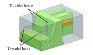
To prevent the workpiece from loosening during clamping, the process pre-drills threaded holes for clamping at the locations where material will be removed from the blank.
Based on the slider’s structure, the process selects M8 threaded holes.
The process positions the threaded holes for the first and second clamping operations at the locations on the slider base where material will be removed, while it places the threaded hole for the third clamping operation at the location of the coolant hole on the back of the workpiece, as shown in Figure 3.
At least two threaded holes are provided on the same clamping surface, with the distance between them corresponding to the clamping plate.
The slider is then secured to the clamping plate using bolts.
After machining is complete, the threaded holes on the slider will be removed or directly used as water passages.
The clamping plate is a reusable tool featuring holes arranged in a standardized pattern; securing the slider blank to the clamping plate with bolts ensures good stability.
The slider requires three setups during machining, and the process presents the following challenges:
① Selecting appropriate reference points and a machining sequence to ensure machining accuracy for the second and third setups after the first setup is completed;
② The small core has relatively small length and width dimensions but a large height dimension.
During machining, it is necessary to prevent deformation of the small core while ensuring its perpendicularity.
Prior to machining, the process analyzes the structure of the 3D model to minimize machining errors and improve machining accuracy.
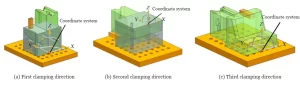
Based on the slider structure, the process selects the midpoint of the edge line on the bottom surface near the slider seat as the reference point.
The process aligns the workpiece coordinate system with the 3D model’s coordinate system.
First, the process machines the slider core with the workpiece clamped vertically; next, the process machines the slider’s bottom surface with the bottom facing upward;
Finally, the process machines the slider’s inclined surface with the inclined surface facing upward, as shown in Figure 4.
To secure the workpiece more effectively, fasten it to the clamping plate with bolts before securing it to the worktable.
The raw material has a relatively low hardness prior to heat treatment.
To extend the service life of the slide block, the material is typically heat-treated to achieve a hardness of 48 HRC.
However, workpieces with high hardness are difficult to machine.
To reduce machining difficulty, the standard process involves rough machining first, followed by heat treatment, and finally finish machining.
Due to the large material removal, high cutting speed, and deep cutting depth during rough machining, the cutting forces generate uneven internal stresses in the workpiece, making it prone to deformation.
After heat treatment, the process precision-grinds all six surfaces of the workpiece to facilitate subsequent machining.
When machining, the process selects different cutting tools based on the material being machined.
Since the slider consists of 718 steel with a hardness of 48 HRC, the process chooses cutting tools with high hardness and good wear resistance, such as cemented carbide inserts, alloy steel tools, or tungsten steel tools.
Use UG software to perform CNC programming for the slider. Select the programming commands for cavity milling toolpaths.
Based on the slider’s dimensions and material, select a φ30R5 mm indexable insert for rough machining.
Since the distance between the small core and the large core is relatively small, the process cannot machine the area between them during roughing.
To prevent the tool from suddenly changing direction at the corner and colliding with the small core, causing deformation, the process sets a fillet in the toolpath at the corner.
Due to the small size of the small core, to prevent deformation, the process strictly controls the depth of cut, with each cut set within 0.5 mm.
Based on the slider’s structure, the total roughing depth is 73 mm.
To ensure the tool shank’s strength, the shank protrusion from the chuck should be set to 75 mm when clamping the tool.
The shorter the shank protrusion, the higher the cutting speed, spindle speed, and feed rate that can be set.
After the φ30R5 mm insert has completed cutting, select the programming commands for the remaining milling paths.
Use a φ16R0.8 mm insert to machine the area between the large and small cores, gradually cutting downward using contour milling.
To prevent overcutting caused by deformation, set the single-side roughing allowance to 1 mm.
The tools and cutting parameters used are shown in Table 1.
| No. | Tool Path Name | Tool Type | Tool Size | Cutting Depth (mm) | Machining Allowance (mm) | Feed Rate (mm·min⁻¹) | Spindle Speed (r·min⁻¹) |
|---|---|---|---|---|---|---|---|
| 1 | Cavity Milling | Ball End Mill | φ30R5 mm | 73 | 1 | 1500 | 2000 |
| 2 | Residual Milling | Ball End Mill | φ16R0.8 mm | 73 | 1 | 2000 | 2500 |
Table 1. Rough Machining Cutting Tools and Cutting Parameters in the Core Direction
The cutting volume in the bevel direction is substantial, and the process requires heat treatment after roughing.
Since the structure in the bevel direction is simple, the process uses a cavity milling toolpath.
After machining with a φ30R5 mm indexable insert, the process does not set any additional toolpaths.
Based on the slider structure, the total roughing depth is 45 mm.
The cutting tools and parameters used are shown in Table 2.
| No. | Tool Path Name | Tool Type | Tool Size | Total Cutting Depth (mm) | Machining Allowance (mm) | Feed Rate (mm·min⁻¹) | Spindle Speed (r·min⁻¹) |
|---|---|---|---|---|---|---|---|
| 1 | Cavity Milling | Ball End Mill | φ30R5 mm | 45 | 1 | 1500 | 2000 |
Table 2. Rough Machining Cutting Tools and Cutting Parameters in the Inclined Surface Direction
Three sides of the slider require finishing, but the three-axis CNC machining center being used cannot rotate the workpiece on its table; therefore, the process performs slider machining in three separate setups.
Taking the semi-finishing operation in the first setup orientation as an example, UG software performs CNC programming.
Based on the slider’s structure, first select a φ16R0.8 mm indexable insert cutter and a φ8 mm flat-bottom carbide cutter.
Use a constant-depth cutting method to machine the side walls and the curved surface on the top of the large core.
Then, use a φ8R4 mm ball-nose cutter to machine the surface on the large core with parallel toolpaths at a 45° angle, setting the cutting allowance to 0.1 mm.
Since the material has high hardness after heat treatment, the process sets the cutting depth or step size to 0.2 mm to extend tool life.
For a small flat surface inside the large core, a φ3 mm flat-bottom carbide end mill machines with a planar cutting path to ensure a machining allowance of 0.1 mm across all areas of the core surface.
Since the ribs on the large core have a thickness of 0.8 mm and a depth of 7 mm, they cannot undergo CNC milling.
After removing the ribs from the 3D model, the process reserves them for EDM machining, eliminating the need for CNC programming for the ribs.
The semi-finishing cutting parameters appear in Table 3.
| No. | Tool Path Name | Tool Type | Tool Size | Total Cutting Depth (mm) | Machining Allowance (mm) | Feed Rate (mm·min⁻¹) | Spindle Speed (r·min⁻¹) |
|---|---|---|---|---|---|---|---|
| 1 | Contour Cutting | Ball Nose Cutter | φ16R0.8 mm | 45 | 0.25 | 1,500 | 2,500 |
| 2 | Contour Cutting | Carbide Cutter | φ8 mm Flat End Mill | 10 | 0.15 | 1,000 | 1,500 |
| 3 | Parallel Cutting | Carbide Cutter | φ8R4 mm Ball End Mill | 10 | 0.10 | 1,000 | 2,000 |
| 4 | Surface Cutting | Carbide Cutter | φ3 mm Flat End Mill | 5 | 0.10 | 300 | 3,000 |
Table 3. Semi-Finishing Tool Path Cutting Parameters
The machining path is shown in Figure 5(a).
Due to the different side structures of the large and small cores, the sides of the large core are beveled.
A φ16R0.8 mm indexable insert machines from top to bottom using a constant-depth cutting method.
The sides of the small core are vertical surfaces.
To ensure the perpendicularity of the small core’s sides, a φ12 mm flat-bottom carbide cutter mills in three layers from the outside in using a contour milling method.
Then, the same φ12 mm flat-bottom carbide cutter finishes the flat surfaces at the bases of the large and small cores.
For the curved surface on the top of the large core, a φ8R4 mm ball-nose cutter machines with parallel passes at a 45° angle.
For the small flat surface inside the large core, a φ3 mm flat-bottom carbide cutter machines with planar passes.
To facilitate mold assembly and polishing, the machining process sets the allowance for the side surfaces and curved surfaces of both cores to 0.02 mm.
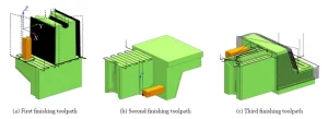
The machining path is shown in Figure 5(b).
First, a φ16R0.8 mm indexable insert finishes the bottom surface of the large core using a face milling process to ensure the flatness of the bottom surface.
The end face of the small core features an arc-shaped structure within a vertical plane, which cannot be machined during the first clamping.
During the second clamping, a φ6 mm flat-bottomed carbide insert performs contour milling.
First, the process performs semi-finishing using a contour-following cutting method, followed by finishing in three layers from the outside in.
The machining path is shown in Figure 5(c).
For the inclined surface of the slider seat, a φ16R0.8 mm indexable insert machines from top to bottom using a constant-depth cutting method.
Additionally, a φ6 mm flat-bottom carbide insert finishes the top surface of the large core using a face-milling process to ensure the flatness of the top surface.
The end face of the large core also features an arc-shaped structure within a vertical plane, which cannot be machined during the first setup.
During the third setup, a φ10 mm flat-bottom carbide cutter performs contour milling: first, it performs semi-finishing using the equal-height cutting method, followed by finishing in three layers from the outside in.
Finally, face milling processes finish the three upper surfaces of the large core to ensure the flatness of the upper surface of the large core.
The transition area between the long strip on the upper surface and the slide block cannot be machined cleanly with a milling cutter; therefore, EDM performs this operation.
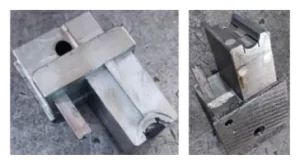
The finished slide block is shown in Figure 6. The finishing cutting parameters for each setup are listed in Table 4.
| Clamping Sequence | No. | Tool Path Name | Tool Type | Tool Size | Cutting Depth (mm) | Feed Rate (mm·min⁻¹) | Spindle Speed (r·min⁻¹) |
|---|---|---|---|---|---|---|---|
| 1st Clamping | 1 | Contour Cutting | Ball Nose Cutter | φ16R0.8 mm | 73 | 1,200 | 2,500 |
| 1st Clamping | 2 | Profile Cutting | Carbide Cutter | φ12 mm Flat End Mill | 73 | 500 | 1,500 |
| 1st Clamping | 3 | Parallel Cutting | Carbide Cutter | φ8R4 mm Ball End Mill | 10 | 1,000 | 2,000 |
| 1st Clamping | 4 | Surface Cutting | Carbide Cutter | φ3 mm Flat End Mill | 5 | 100 | 3,000 |
| 2nd Clamping | 1 | Surface Cutting | Ball Nose Cutter | φ16R0.8 mm | 10 | 1,200 | 2,500 |
| 2nd Clamping | 2 | Profile Cutting | Carbide Cutter | φ6 mm Flat End Mill | 10 | 300 | 2,000 |
| 3rd Clamping | 1 | Contour Cutting | Ball Nose Cutter | φ16R0.8 mm | 45 | 1,200 | 2,500 |
| 3rd Clamping | 2 | Surface Cutting | Carbide Cutter | φ10 mm Flat End Mill | 10 | 500 | 1,500 |
| 3rd Clamping | 3 | Profile Cutting | Carbide Cutter | φ10 mm Flat End Mill | 10 | 500 | 1,500 |
Table 4. Finishing Cutting Parameters
Plastic mold sliders have a relatively complex structure, with the core section typically featuring irregular curved surfaces that require machining on all four sides.
Since mold manufacturers generally use three-axis machining centers, the slider structure necessitates multiple setups and cutting from different angles to produce a slider that meets specifications.
Sliders require high hardness, and some may require heat treatment.
It is necessary to develop corresponding machining processes based on the specific structure and material of each slider, select appropriate cutting tools and parameters, and determine reference points and design mounting methods according to the slider’s structure to improve machining quality.

