How to efficiently machine shaped parts on CNC mill-turn machines?


The surface roughness value of a part reflects its surface quality and determines its mechanical properties and assembly characteristics.
A part’s surface roughness is influenced by various factors, including the machining method, parameters, and techniques. Milling is an important metal-cutting process widely used in the machining of various parts.
Studying the factors affecting surface roughness during the milling process is of great significance for improving machining efficiency.
Current research on the surface roughness of milled parts primarily focuses on two areas. The first concerns the influence of machining parameters on surface roughness.
Existing studies mainly examine how machining parameters—such as feed rate, spindle speed, cutting depth, and cutting width—affect surface roughness during the milling of materials like aluminum alloys, titanium alloys, and high-strength steel;
The second is the influence of geometric and physical factors during the machining process on surface roughness.
Researchers have analyzed residual area height produced by ball-nose end mills. This study derived the relevant calculation formulas accordingly. It proposed roughness control strategies to regulate residual height.
It also built a sector-shaped residual model to evaluate how machining parameters affect the residual area. Other scholars investigated the determinants of residual area height during side milling. This study developed calculation software for this geometric parameter.
It constructed independent envelope models for climb milling and conventional milling. Quantitative analysis described how these two cutting modes modify surface roughness. Their work considered flat, convex and concave curved surfaces under side-milling conditions.
Shi Lichen and co-authors constructed a dynamic model describing tool-workpiece vibration. Cutting experiments verified the accuracy of this model. Wavelet packet energy extracted from vibration signals of tool-tip acceleration can characterize surface roughness.
A separate line of research focuses on the formation mechanisms of surface roughness. Theoretical modelling serves as the main approach within this branch. These models guide the selection and optimization of milling process parameters.
This direction remains a vital research topic for surface roughness studies. Most existing literature prioritizes geometric factors represented by residual machining height. Researchers have paid less attention to physical factors.
These factors include plowing and shearing interactions between the cutting tool and workpiece. Furthermore, most existing studies focus on ball-nose end mills and mainly examine side milling.
They rarely investigate the widely used end milling process with standard end mills. This paper examines the factors influencing surface roughness in end milling by analyzing both geometric and physical factors.
The height of the remaining surface area is the most significant geometric factor affecting surface roughness.
In milling operations, the cutting tool produces the residual surface area through discontinuous cutting of the workpiece along the feed path.
Milling falls into two main categories: side milling and face milling. The two modes generate residual cutting areas through distinct mechanisms.
Side milling mainly machines the outer contours of workpieces and uses the side cutting edge of an end mill.
The side cutting edge generates the residual cutting area via discontinuous cutting during feeding, and the end mill diameter mainly affects the residual height.
Face milling primarily processes flat surfaces, grooves, and cavities and relies on the end mill’s bottom cutting edge. The bottom cutting edge creates the residual area through discontinuous cutting in the feed motion.
The radius of the tool tip rounding and the bottom edge clearance angle mainly govern its height.
The tip radius and rake face are the primary working areas of the tool that cause plowing action on the workpiece during end milling, resulting in effects such as extrusion, sliding, accumulation, and tearing.
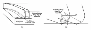
Figure 1 illustrates the formation of residual machined area by the tip radius of the bottom cutting edge. Since an end mill has multiple cutting edges, its cutting process is discontinuous.
Each cutting edge performs circumferential cutting while also achieving radial feed, with the feed rate equal to the feed per tooth (fz). fz separates the tips of two adjacent cutting edges in the radial cross-section.
The cutting tool cannot fully remove the workpiece material within this distance, and the leftover material forms the machining residual area.
Figure 1(a) shows the positions of the cutting edges of two adjacent teeth at a certain radial cross-section during the machining process;
The shaded area represents the residual machining area at that cross-section. As can be seen from the figure, the residual machining area during end milling is not constant but first gradually increases and then gradually decreases.
The height of the machining residue area is also not uniform throughout; It is highest near the centerline along the machining feed direction. We select the cross-section with the maximum residual height for calculation.
Figure 1(b) presents the calculation result. O1 and O2 denote the rounding centers at the tips of two adjacent cutting edges.
This figure tracks these adjacent cutting edges. The edges occupy different positions at separate moments, and all positions belong to the same machining cross-section.
The length of line DE is the feed per tooth (fz), and the height of line GF represents the height of the machined residual area, which is the primary geometric factor affecting surface roughness.
Line BE represents the secondary cutting edge of the root face, and ∠E is the root face clearance angle (Kγ), typically ranging from 1° to 3°.
The secondary cutting edge participates in the machining of the residual area, and the root face clearance angle is one of the primary factors affecting the height of the residual machined area.
As can be seen in Figure 1(b):
GF=O1D-O1C (1)
In the equation: O1D = O1G = R, where R is the radius of the rounded tip of the bottom edge.
In triangle Rt△O1CG, CG is one leg, and O1C is the other leg; therefore, O1C can be expressed as:
O1C=Rsin∠CGO1 (2)
Based on the geometric relationships, we can see that:
∠BGC=∠E
∠CGO1=∠BGC+∠BGO1=∠E+∠BGO1 (3)
Then:
sin∠CGO1=sin(∠E+∠BGO1)(4)
In Rt△BDE:
BD = DE tan E = fz tan E
Then:
O1B=O1D-BD=R-fztan E
It can be seen that:
O1H=O1Bcos∠HO1B
And:
∠HO1B=∠E
Substituting O1B and ∠E yields:
O1H=O1Bcos∠HO1B
=(R-fztan E)cos E
=Rcos E-fzsin E
In △HGO1:
sin∠HGO1=O1H/O1G=O1H/R
=(Rcos E-fzsin E)/R
=cos E-(fz/R)sin E (5)
It is clear that:
sin∠HGO1=sin∠BGO1
Substituting Equation (5) into Equation (4) yields:
sin∠CGO1=sin(∠E+∠BGO1)
=sin(∠E+arcsin(sin∠BGO1))
=sin(∠E+arcsin(cos E-(fz/R)sin E))(6)
Substituting Equations (2) and (6) into Equation (1) yields the height of the machining residue area, GF, as:
GF=R-O1C=R-Rsin∠CGO1
=R-Rsin(∠E+arcsin(cos E-(fz/R)sin E))(7)
As can be seen from Equation (6), the height of the machining residue area depends only on the radius of rounding R at the bottom cutting edge, the feed per tooth fz, and the bottom cutting edge clearance angle Kγ;
It is unrelated to the cutting depth or milling width during the milling process.
Reducing both the radius R of the bottom-edge tool tip rounding and the bottom-edge clearance angle Kγ can lower the height of the machined residual area, thereby reducing the surface roughness value.
This study must evaluate the relationship between the feed per tooth fz and the height of the residual machined area together with variations in the rounded-tip radius of the bottom cutting edge (R).
Only when the radius of the rounded tip remains constant will reducing fz decrease the height of the residual machined area.
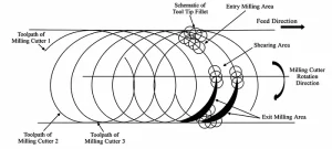
Figure 2 shows a cross-sectional view of the radial motion of a three-flute end mill, illustrating the trajectories of the three cutting edges during the machining process.
The tool rotates clockwise, and the feed direction is from left to right. The trajectory lines represent the centerline paths of the side-edge tip rounding.
We plot the tool tip rounding circles along the paths of any two cutting edges. The upper cutting edge enters the cut inside the overlapping zone of these two rounding circles.
These circles belong to two neighboring cutting edges.
The two tool tip rounding circles primarily affect the residual machining area in this region and yield a smaller area with a lower height.
As the tool continues to rotate clockwise, the trajectories of the adjacent cutting edges’ rounded tips gradually diverge.
The secondary cutting edge on the tool’s bottom edge mainly affects the machined residual area, and the bottom edge clearance angle determines the residual area height.
At this point, the machined residual area is larger and has a greater height;
As the tool continues to rotate and enters the lower exit zone, the rounded trajectories of the adjacent cutting edges’ tips gradually overlap again.
The tip rounding primarily affects the machined residual area and produces a smaller residual area with a lower height.
The residual height on the machined surface is greatest near the centerline in the feed direction, but this does not necessarily mean that the surface roughness value is highest near the centerline.
During end milling, in addition to the height of the residual material area affecting surface roughness, the tool’s actions on the workpiece—such as extrusion, shearing, sliding, and tearing—also influence surface roughness.
We group these behaviors under the term tool-workpiece interactions. We further classify these interactions into plowing and shearing effects.
These two effects act as the main physical factors that shape surface roughness. Researchers typically define high-speed milling with a spindle speed above 1500 r/min.
High-speed milling uses a much smaller feed per tooth than conventional milling. This feed value ranges from 0.01 to 0.1 mm and sits at the same magnitude as the cutter tip radius.
At this point, the cutting edge is no longer sharp, and the cutting conditions change. There exists a critical cutting thickness; only when the cutting thickness exceeds this critical value is it possible to remove material from the workpiece and form a chip.
We call this critical cutting thickness the minimum cutting thickness h. It changes with workpiece material and cutting speed. Its value equals roughly 0.2 times the tool tip rounding radius.
Figure 3 demonstrates this cutting phenomenon. When the cutting thickness h exceeds the bifurcation height h’, the rounded tool tip exerts shear force on the workpiece material, and chips form accordingly.
For the second condition where h falls below h’, the rounded tool tip induces plowing rather than shearing. Material flows toward the rear rake face. This material movement generates the finished surface without chip formation.
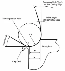
Figure 2 shows the initial contact between the cutting edge tip and the workpiece. The cutting depth stays below the minimum cutting depth at this moment. The tool fails to shear into the workpiece material. No chips form in this state.
This is primarily due to the rounded tip of the cutting edge exerting pressure on the workpiece surface, causing plastic deformation and slight tearing;
Extrusion and sliding dominate the cutting process (the “plowing zone” in Figure 2) and produce poor surface quality and high surface roughness values.
As the tool continues to rotate, the cutting depth at the tool tip gradually increases;
When the cutting depth exceeds the minimum cutting depth, the tool forms chips, and shearing mainly characterizes the cutting process (the “Shearing Zone” in Figure 2). Surface quality in this zone is relatively good, and surface roughness values are low.
As the tool continues to rotate, the tool tip enters the “Exit Plowing Zone.”
The interaction between the tool and the workpiece in this zone differs slightly from that in the entry plowing zone.
When the tool tip enters this zone, its direction of motion begins to gradually shift toward the opposite direction of the feed, while simultaneously maintaining movement in the feed direction.
Consequently, the rounded tool tip and the rake face exert continuous and significant extrusion and sliding friction on the workpiece material, resulting in substantial material buildup.
Once the buildup height exceeds the minimum cutting thickness, chips begin to form. Plowing and intermittent shearing prevail inside this zone. These actions produce higher surface roughness.
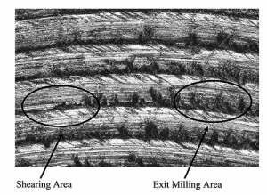
Figure 4 displays obvious material extrusion, sliding friction, and buildup within the exit plowing zone. These phenomena degrade the final surface quality.
Figure 2 marks three distinct regions: the entry plowing zone, shear zone, and exit plowing zone. Feed per tooth changes alter how the tool and workpiece interact within these zones.
When the feed per tooth is less than the minimum cutting thickness, even in the “Shear Zone,” chips cannot form;
The tool squeezes the workpiece surface and controls this interaction. Most material within the cutting thickness gets pushed under the tool tip rounding.
This squeezed material forms part of the finished machined surface. At this point, the tool-workpiece interaction in all three zones is dominated by extrusion;
The feed per tooth can rise above the minimum cutting thickness. It may even exceed the radius of the tool tip rounding. The tool applies extrusion, sliding, material buildup and tearing to the workpiece.
These forces gradually take charge inside the shear zone. Larger feed per tooth amplifies these mechanical effects. Their influence on surface roughness grows stronger.
Meanwhile, shear forces contribute less and less to the final surface roughness.
The machine tool used was a DMG DMU50 five-axis CNC machining center, with a maximum rated spindle speed of 10,000 r/min and a maximum feed rate of 2,000 mm/min.
The cutting tool is an 8-mm-diameter three-flute end mill with a bottom-edge rounding radius of 0.1 mm, a bottom-edge clearance angle of 3°, and a tool material of cemented carbide.
The workpiece is 6061 aluminum alloy, with blank dimensions of 200 mm × 150 mm × 50 mm. This study measured surface roughness using a Mitutoyo SJ-210 handheld roughness tester. It adopted an orthogonal experimental design for groove milling under wet cutting conditions.
This experiment included 13 levels for the spindle speed factor, 1 level for the feed rate factor, and 1 level for the cutting depth factor, as shown in Table 1.
In accordance with the principles of orthogonal experimentation, a total of 39 sets of cutting tests were conducted.
After clamping the workpiece, this study first machined its top surface with a face mill to ensure flatness and then carried out slot milling.
For each machined surface, this study took measurements at three positions near the centerline using the roughness tester and adopted the average as the final surface roughness of the surface.
| Spindle Speed, n (r/min) | Feed Rate, f (mm/min) | Depth of Cut, aₚ (mm) |
|---|---|---|
| 1,400, 1,600, 3,000, 4,000, 4,200, 4,800, 5,000, 5,400, 5,800, 6,200, 6,500, 7,000, 8,500 | 200 | 2 |
Table 1. Machining Parameters for Milling Experiments
This study carried out the tests according to the above protocol and lists the results in Table 2.
| No. | Spindle Speed, n (r/min) | Feed Rate, f (mm/min) | Feed per Tooth, fz (mm/tooth) | Measured Surface Roughness, Ra (μm) | Theoretical Surface Roughness, Ra (μm) |
|---|---|---|---|---|---|
| 1 | 1,400 | 200 | 0.0476 | 0.423 | 0.311136 |
| 2 | 1,600 | 200 | 0.0417 | 0.278 | 0.264053 |
| 3 | 3,000 | 200 | 0.0222 | 0.0905 | 0.118548 |
| 4 | 4,000 | 200 | 0.0167 | 0.084 | 0.080713 |
| 5 | 4,200 | 200 | 0.0159 | 0.0921 | 0.075525 |
| 6 | 4,800 | 200 | 0.0139 | 0.0612 | 0.062846 |
| 7 | 5,000 | 200 | 0.0133 | 0.0611 | 0.059378 |
| 8 | 5,400 | 200 | 0.0123 | 0.0535 | 0.053311 |
| 9 | 5,800 | 200 | 0.0115 | 0.0498 | 0.048192 |
| 10 | 6,200 | 200 | 0.0108 | 0.0588 | 0.043823 |
| 11 | 6,500 | 200 | 0.0103 | 0.0525 | 0.040951 |
| 12 | 7,000 | 200 | 0.0095 | 0.0477 | 0.036791 |
| 13 | 8,500 | 200 | 0.0078 | 0.0514 | 0.027381 |
Table 2. Experimental Results
It computed the height of the residual machined area via Equation (6).
After converting the units to μm, this study found that the Ra value was approximately 0.2 times this height.
This calculation produces the theoretical roughness value, which this study included in Table 2 for comparison.
This study sorted the calculated theoretical surface roughness values and the measured values by different feed rates, as shown in Figure 5.
Analysis of Table 2 and Figure 5 reveals the following:
This range falls within the machine tool’s low-speed region;
Specifically, at 1,400 r/min, the machine is still operating within its constant-torque range, resulting in low cutting power and an unstable cutting process.
Due to the low rotational speed, the feed per tooth is relatively large in this range. Strong extrusion and sliding friction occur between the tool and workpiece.
Workpiece material also shows obvious tearing and accumulation. Cutting system instability and tool plowing dominate surface roughness in this condition. The residual machining height only plays a secondary role.
Consequently, there is a significant discrepancy between the theoretical and measured roughness values.
This speed range constitutes the machine tool’s primary cutting speed zone, where vibrations in the cutting system are minimal and the cutting process is stable.
Additionally, the minimum feed per tooth in this speed range is 0.0123 mm/r (at 5,400 r/min), which is greater than the minimum cutting depth.
Shear dominates the cutting motion, and the height of the residual machined area mainly affects the surface roughness of workpieces in this range. The theoretical roughness values and measured values show good agreement.
This speed range represents the high-speed range for the machine tool. The maximum feed per tooth during the cutting process is only 0.0115 mm/r (at 5,800 r/min).
Even this maximum value falls below the minimum cutting thickness, so the tool generates no chips. The cutting action is primarily driven by the extrusion force exerted by the tool on the workpiece.
When the accumulation of material resulting from extrusion exceeds the minimum cutting thickness, a shearing action occurs, forming a chip.
Therefore, the shearing action in this process is intermittent, and the extrusion of the workpiece by the tool is the primary mechanism.
Extrusion-induced surface irregularities mainly affect surface roughness at this point, while residual machining height exerts only a minor influence.
These irregularities do not change significantly with increasing rotational speed;
Accordingly, surface roughness changes slightly within this speed range, and measured roughness exceeds the theoretical values.
Figure 5 Comparison of measured and theoretical roughness values at different rotational speeds
In face milling, the primary geometric factor affecting surface roughness is the height of the residual machined area;
The primary physical factor is the tool-workpiece interaction, specifically plowing and shearing effects.
The residual machined area is primarily caused by discontinuous cutting during the feed process.
Unlike in side milling, where the residual machined area is primarily influenced by the tool radius, in face milling, it is affected by the radius of the rounded tip on the bottom edge and the clearance angle of the bottom edge.
The residual machined area and its height are smallest when the tool tip enters and exits the workpiece, and largest near the centerline of the cut.
Tool-workpiece interaction is primarily related to changes in cutting depth during the machining process.
In the areas where the cutting edge enters and exits the workpiece, the cutting depth is less than the minimum cutting depth;
The plowing action of the tool on the workpiece is primarily characterized by extrusion, sliding, tearing, and accumulation.
In the area near the centerline, where the cutting depth exceeds the minimum cutting depth, the interaction between the tool and the workpiece is primarily shear-based.
When the feed per tooth is less than the minimum cutting thickness, chips cannot be formed even in the shearing zone;
Instead, the interaction is dominated by plowing actions such as extrusion and sliding. Cutting tests yield theoretical roughness values from residual area height calculations.
These values match measured data well within the main cutting speed range. Obvious deviations appear under low cutting speeds and high cutting speeds.
Plowing behavior dominates surface roughness at low speeds. The tool squeezes the workpiece and generates sliding friction. These effects outweigh the influence of geometric residual height. Extrusion-induced plastic deformation becomes the dominant factor at high speeds.
This deformation largely determines the final surface roughness.