How to efficiently machine shaped parts on CNC mill-turn machines?



The guidance system housing uses cold-worked forged 7075 aluminum alloy. It has a complex structure and typical thin-walled housing features.
Unlike conventional enclosure housings, it contains bearings, worm gears, and other precision transmission components. Therefore, its geometric tolerances are extremely strict.
Figure 1 shows several structural features of the guidance system housing. Its main geometric elements include thin-walled square and semicircular deep cavities.
The structure includes bearing bores, worm gear mounting positions, and other critical features. These features create demanding machining requirements.
The operating environment and design requirements specify cold-forged 7075 aluminum alloy plate as the blank material. Material removal exceeds 93%.
Uneven release of internal material stress can easily cause twisting and deformation during machining.
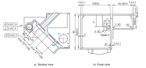
The part includes mounting positions for bearings and worm gear transmission components. These areas must withstand certain torque and impact loads.
For this reason, 7-series aerospace aluminum provides a suitable material choice.
The part contains many thin walls and deep cavities, with a material removal rate exceeding 93%. Reinforcing ribs have widths and thicknesses of less than 5 mm.
These thin structures are unsuitable for clamping and positioning. Therefore, the process requires an additional clamping boss.
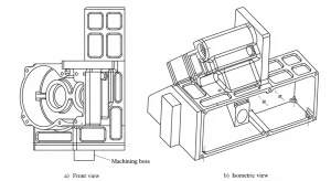
Figure 1a shows this boss at the far-left feature. A dedicated fixture removes the boss after other areas receive finish machining.
This approach ensures the component’s final geometry.
The selected material is cold-worked forged 7075 aluminum alloy. The blank dimensions are 135 mm × 130 mm × 190 mm.
Cold-worked forged 7075 aluminum alloy usually retains significant internal stress after manufacturing. Machining introduces additional stresses through cutting forces and heat.
Tool compression causes plastic deformation in the surface metal. The undeformed internal material restricts this deformation, creating residual tensile stress.
Friction between the tool flank and machined surface can create residual compressive stress.
Cutting heat expands the surface metal while cooler internal material restricts expansion. Cooling then restricts shrinkage and produces residual tensile stress.
If temperatures exceed the phase-transformation threshold, structural changes can alter material volume. This change may create residual tensile or compressive stress.
The blank therefore requires thermal stress relief before machining. This treatment supports dimensional accuracy and required material properties.
After rough machining, vibration aging removes machining-induced stress. Deep cryogenic treatment follows the semi-finishing stage.
7075 aluminum is an Al-Zn-Mg-Cu ultra-high-strength aluminum alloy. Its high strength requires greater cutting forces than common alloys such as 6061.
Its hardness is approximately 150 HBW, and tool wear can become significant. Therefore, cutting tools need excellent wear resistance.
Its high strength and hardness can still support excellent surface quality under suitable machining parameters. This makes 7075 suitable for precision structures.
The process uses HSK rear-pull toolholders and milling cutters designed for aluminum. Roughing parameters require careful control.
Cutting speed ranges from 100 to 200 m/min. Feed ranges from 0.05 to 0.20 mm/z, with 1–2 mm cutting depth.
The machining route follows an analysis of the housing structure and geometric tolerances. Table 1 presents the complete process design.
| Operation | Operation Name | Description | Applicable Standard |
|---|---|---|---|
| OP10 | Incoming Inspection | Inspect blank appearance, dimensions, metallographic structure, and material integrity. | AMS-QQ-A-250/4 |
| OP20 | Heat Treatment | Perform heat treatment to relieve internal material stress. | GB/T 16638-2013 |
| OP30 | Three-Axis Milling | Mill a 110 mm × 30 mm × 20 mm process boss. Maintain a total remaining height of 170 mm. | HB5800-1999 |
| OP40 | Five-Axis Machining | Clamp the process boss with a self-centering vise. Rough-machine the housing profile and cavities with 1.5 mm stock per side. | HB5800-1999 |
| Rough-machine holes ≥6 mm while leaving 0.5 mm stock per side. Break sharp edges with C0.5 chamfers. | |||
| OP50 | In-Process Inspection | Inspect dimensions against the semi-finished process drawing. | HB5800-1999 |
| OP60 | Aging Treatment | Perform vibration aging according to specifications to relieve machining stress. | GB/T 25712-2010 |
| OP70 | Five-Axis Machining | Clamp the process boss with a self-centering vise. Semi-finish the housing profile and cavities. | HB5800-1999 |
| Leave 0.25 mm stock on the Ø24, Ø48, and Ø13 holes and end faces. Finish all other features. | |||
| OP80 | In-Process Inspection | Inspect dimensions against the semi-finished process drawing. | HB5800-1999 |
| OP90 | Cryogenic Treatment | Perform cryogenic cycling according to specifications to stabilize dimensions. | JB/T 14737-2024 |
| OP100 | Five-Axis Machining | Finish hole-end surfaces and precision-bore the holes. Drill and tap threaded holes and chamfer openings to C0.5. | HB5800-1999 |
| OP110 | In-Process Inspection | Inspect dimensions against the semi-finished process drawing. | HB5800-1999 |
| OP120 | Wire EDM | Remove the process boss using wire EDM. | HB5800-1999 |
| OP130 | EDM | Machine the 4 mm × 7 mm × 36 mm slot using electrical discharge machining. | HB5800-1999 |
| OP140 | In-Process Inspection | Inspect dimensions against the semi-finished process drawing. | HB5800-1999 |
| OP150 | Three-Axis Milling | Finish the weight-reduction pockets and counterbores near the former process boss. | HB5800-1999 |
| Mill the M16 × 1.5 thread and break sharp edges with C0.5 chamfers. | |||
| OP160 | Final Inspection | Inspect all dimensions against the finished-part drawing and applicable technical specifications. | HB5800-1999 |
Table 1. Process Design
Milling thin-walled aluminum housings requires high efficiency, low cutting forces, effective chip evacuation, and strong vibration resistance. These characteristics reduce deformation and protect surface quality.
Tool diameters range from Ø3 to Ø20 mm. Two-flute or three-flute designs are suitable, while two-flute tools improve chip evacuation.
A helix angle of at least 40° improves chip removal. The rake angle should reach at least 7°.
The clearance angle should reach at least 10°. These geometries maintain cutting sharpness and reduce friction.
An ultrafine-grain carbide substrate improves wear resistance and reduces edge chipping.
A Ø50 mm face mill uses four PCD-coated cutting edges. It is suitable for rough machining.
Cutting speeds can reach 1,000–2,000 m/min.
TiAlN, or H2 coating, provides stronger high-temperature resistance. It suits high-speed dry cutting and difficult aluminum alloys such as 7075.
TiCN + Al2O3, or M2 coating, offers good wear resistance at medium cutting speeds. It suits conventional aluminum alloys.
Large chip flutes and small tooth pitches improve chip evacuation. Cutting edges should receive precision grinding to below Ra 0.4 μm.
This geometry reduces chip adhesion. Large positive-rake milling cutters are preferable, while negative-rake tools should be avoided.
Tool overhang should remain short because of the housing geometry. The design must also prevent toolholder interference during five-axis machining.
Machining cost also affects toolholder selection. Therefore, the process uses HSK rear-pull taper toolholders.
The rear-pull structure contacts the spindle face through its flange. This configuration increases connection rigidity and supports heavy cutting.
Some models can withstand torque up to 1,200 N·m. They remain stable at spindle speeds reaching 2,800 r/min.
The rear-pull design uses dual-surface contact. Repeatability can reach ±2 μm, supporting consistent machining results.
The toolholder supports high-speed operation with preset balancing below G2.5. This capability helps suppress chatter when machining thin-walled components.
Table 2 lists the tools selected according to the preceding analysis.
| Tool No. | Tool Name | Tool Specification/mm | Toolholder Specification | Machining Type |
|---|---|---|---|---|
| 1 | Face Mill | Ø50 | HSK40FMB22 | Roughing |
| 2 | Flat End Mill | Ø16 | HSK40-ER32 | Roughing / Finishing |
| 3 | Flat End Mill | Ø10 | HSK40-DC08-120L | Roughing / Finishing |
| 4 | Bull-Nose End Mill | Ø4R1.0 | HSK40-DC08-120L | Finishing |
| 5 | Bull-Nose End Mill | Ø6R1.0 | HSK40-DC08-120L | Finishing |
| 6 | Flat End Mill | Ø6 | HSK40-DC08-120L | Finishing |
| 7 | Chamfer Mill | Ø8 × 90° | HSK40-DC08-120L | Chamfering |
| 8 | Spot Drill | Ø6 | HSK40-DC08-120L | Hole Positioning |
| 9 | Ball End Mill | Ø6R3.0 | HSK40-DC08-120L | Surface Finishing |
| 10 | Ball End Mill | Ø4R2.0 | HSK40-DC08-120L | Surface Finishing |
| 11 | Carbide Drill | Ø12.1 | HSK40-ER32 | Drilling |
| 12 | Carbide Drill | Ø2.5 | HSK40-DC08-120L | Drilling |
| 13 | Carbide Drill | Ø3.2 | HSK40-DC08-120L | Drilling |
| 14 | Carbide Drill | Ø3.3 | HSK40-DC08-120L | Drilling |
| 15 | Carbide Drill | Ø1.5 | HSK40-DC08-120L | Drilling |
| 16 | Carbide Drill | Ø2.0 | HSK40-DC08-120L | Drilling |
| 17 | Boring Tool | Ø24 | HSK40-NBH2084 | Boring |
| 18 | Boring Tool | Ø19 | HSK40-NBH2084 | Boring |
| 19 | Boring Tool | Ø48 | HSK40-NBH2084 | Boring |
| 20 | Reamer | Ø13 | HSK40-ER32 | Reaming |
| 21 | Tap | M2.5 | HSK40-DC08-120L | Tapping |
| 22 | Tap | M3 | HSK40-DC08-120L | Tapping |
| 23 | Tap | M4 | HSK40-DC08-120L | Tapping |
Table 2. Tool List
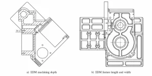
Figure 2 shows the feature requiring electrical discharge machining. The slot lies close to the sidewall and has a narrow width.
Its depth exceeds 33 mm. A conventional end mill cannot provide a suitable large tool diameter.
The required tool overhang would exceed 45 mm. Machining under these conditions would create visible chatter marks on the slot walls.
The overhang would also exceed three times the tool diameter. Such an arrangement cannot provide reliable rigidity.
Poor rigidity would make slot dimensions unstable. Therefore, EDM provides a more suitable method for machining this feature.
OP120 removes the process boss shown in Figure 3. Conventional milling would generate significant cutting stress during this operation.
The stress could deform surfaces that already received finish machining. The thin walls also provide limited structural strength.
They cannot withstand high cutting forces. Part displacement could therefore occur during machining.
Slow-wire EDM removes the process bosses with much lower mechanical cutting stress.
Wire EDM removes the process boss before OP150. Most walls are thin and unsuitable as direct clamping surfaces.
Only the flange around the Ø48 mm hole has an 8 mm thickness. This area provides sufficient material for clamping.
The Ø48 mm and Ø13 mm holes therefore serve as positioning datums, as Figure 4 shows.
A dedicated positioning fixture and clamping plates secure the workpiece. Machining then finishes the weight-reduction pockets and counterbores.
The operation also mills the M16 × 1.5 thread. Figure 5 shows the three-axis setup for OP150.
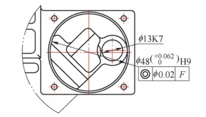
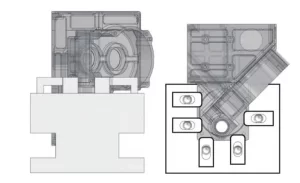
Figure 6 shows a machining region with a cavity depth of 56.5 mm. Its smallest corner radius is R2.0 mm.
Traditional fixed-axis finishing would require a Ø4R2.0 mm ball end mill. Tool overhang would exceed 57 mm.
This length equals 14.25 times the tool diameter. Such an overhang would significantly reduce tool rigidity.
NX CAM’s Variable Axis Guiding Curves strategy reduces the overhang to 30 mm. This change greatly increases tool rigidity.
It also reduces tool vibration during machining.
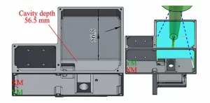
Create a new operation and select the multi-axis machining operation type. Then select Variable Axis Guiding Curves.
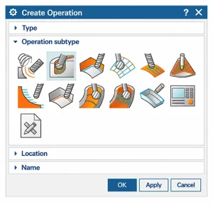
Select the cavity side and bottom surfaces as the machining area. Set the drive type to Morph.
Specify two guide curves along the upper and lower cavity edges. Figure 8 shows the corresponding selections.
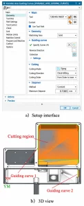
Set the cutting pattern to reciprocating to reduce tool retraction. This setting improves machining efficiency.
Set the cutting direction along the guide curves. Start from Guide Curve 1 and machine downward.
Specify a machining stepover of 0.1 mm.
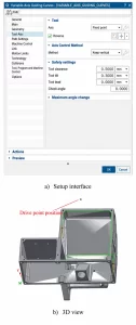
Set the tool axis to Point Toward, as Figure 9 shows. Specify a 0.3 mm clearance between toolholder and workpiece.
Set the Tool Holder Clearance parameter to 0.5 mm. Place the drive point at the cavity center.
Raise the point 120 mm above the upper surface datum.
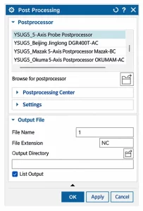
Use the NX CAM five-axis postprocessor shown in Figure 10. It outputs G-code and auxiliary M-code for the CNC machine.
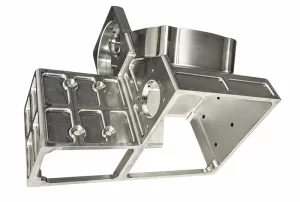
The following section shows part of the postprocessed CNC code. Figure 11 shows the actual machining result.
(==========TOOL LIST START=========)
(T29 | H29 | D00 | 90.857 | T29B4 BALL END MILL, MINIMUM TOOL LENGTH 45mm, TAPER SHANK DC08-120L)
(==========TOOL LIST END===========)

G17 G40 G49 G80
G00 G90 G53 Z0.
(VARIABLE_AXIS_GUIDING_CURVES)
N1 T29 M06
S7500 M03
(T29B4 BALL END MILL, MINIMUM TOOL LENGTH 45mm, TAPER SHANK DC08-120L D=4.000 R=2.000)
G49
G54
G00 G90 A-112.2447 C95.7253
G68.2 X0.0 Y0.0 Z0.0 I-84.2747 J112.2447 K180.
G53.1 P2
G00 G90 X-36.2861 Y57.2267 M08
G49
G69.2
G05A0.05E0.005T0.06
G43.4 H29
G00 G90 X-58.5 Y-42.3332 Z-87.3628 A-112.2447 C95.7253
X-.9352 Y-36.5618 Z-63.7006
G01 X1.489 Y-36.3187 Z-62.7041 F1500.
X1.8499 Y-36.3565 Z-62.5558
X2.1971 Y-36.4697 Z-62.4131
X2.5172 Y-36.6539 Z-62.2815
X2.7979 Y-36.9021 Z-62.1661
X3.0285 Y-37.2048 Z-62.0714
X3.1999 Y-37.5502 Z-62.0009
X3.3058 Y-37.9252 Z-61.9574
X3.342 Y-38.3153 Z-61.9425
X3.3439 Y-39.5257 Z-61.9418 A-112.2691 C94.9807
X3.3455 Y-40.7361 Z-61.9412 A-112.2902 C94.2345
X3.3469 Y-41.9466 Z-61.9407 A-112.3079 C93.4868
X3.3481 Y-43.1571 Z-61.9402 A-112.3222 C92.738
X3.3489 Y-44.3677 Z-61.9399 A-112.333 C91.9882
X3.3495 Y-45.5783 Z-61.9397 A-112.3404 C91.2377
X3.3498 Y-46.7889 Z-61.9396 A-112.3444 C90.4868
X3.3499 Y-47.9995 Z-61.9397 A-112.3449 C89.7357
X3.3496 Y-49.2101 Z-61.9398 A-112.3419 C88.9847
X3.3491 Y-50.4207 Z-61.94 A-112.3355 C88.2341
X3.3483 Y-51.6313 Z-61.9404 A-112.3256 C87.484
This study examines a thin-walled 7075 aluminum housing for a guidance system. The component combines complex geometry, high material removal, strict tolerances, and deformation risks.
A complete machining process and dedicated tooling system address these challenges. NX CAM also supports optimized five-axis precision machining.
The process uses multistage stress control, carefully selected cutting tools, suitable toolholders, and customized fixtures. Variable Axis Guiding Curves further improve machining stability.
These measures address difficult clamping, tool chatter, and dimensional accuracy problems. They also keep part deformation within allowable limits.
The process satisfies geometric tolerances at bearing and worm gear mounting locations.
The complete solution integrates CAXA CAPP process planning and NX CAM five-axis programming. It also combines EDM, wire EDM, aging, and cryogenic treatment.
Together, these methods create a standardized process for high-precision, thin-walled aluminum housings.
Actual five-axis machining confirms the process can maintain machining accuracy and surface quality. Optimized toolpaths and improved rigidity also increase machining efficiency.
The same improvements extend cutting-tool life. This process provides a repeatable technical reference for similar complex thin-walled components.

