How to efficiently machine shaped parts on CNC mill-turn machines?
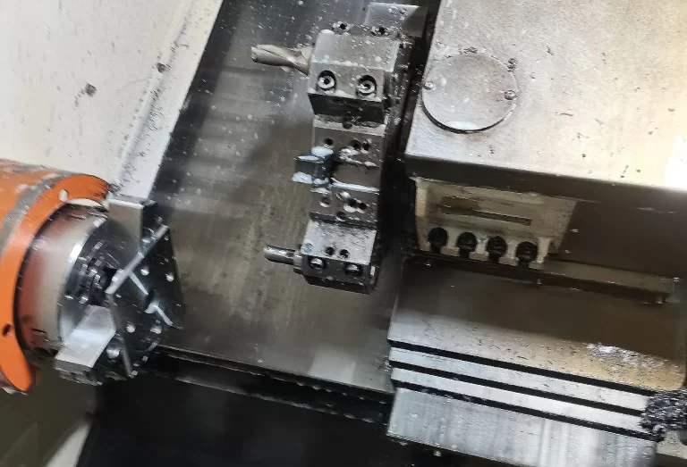


Combined turning and milling technology utilizes the rotational motion of the milling cutter and the workpiece to achieve a highly efficient and precise machining process.
We compare this method with conventional turning processes. Turn-milling composite machining lowers the required workpiece rotational speed.
It also cuts radial cutting forces substantially. This approach weakens centrifugal loads on the workpiece.
It further reduces radial loads acting on the cutting tool. These improvements raise the final machining accuracy and surface quality of the parts.
Turn-milling composite cutting transforms continuous turning into intermittent milling. This method facilitates chip breaking and reduces cutting temperature effectively.
Titanium alloys deliver outstanding physical and mechanical properties. Engineers widely adopt these materials for core components in aerospace and defense sectors.
Titanium alloys exhibit high chemical reactivity. Cutting temperature exerts a substantial influence on the finished surface quality of titanium alloy workpieces.
The author designed orthogonal turn-milling tests for titanium alloys. These experiments investigated the effects of cutting parameters on cutting temperature and surface roughness.
Test results demonstrate the distinct advantages of this composite machining technique.
The findings also provide a theoretical foundation for turn-milling of titanium alloy components.
TC11 titanium alloy possesses excellent thermal strength and room-temperature strength and is widely used in the manufacture of aircraft engine components.
This paper selected TC11 titanium alloy as the experimental material; Its chemical composition and mechanical properties are listed in Tables 1 and 2, respectively.
The milling cutter is a solid carbide tool manufactured by Zhuzhou Diamond Cutting Tools Co., Ltd., model VSM-4E-D6.0.
This milling cutter features a variable helix angle design and an AlTiN coating.
Its structural parameters are as follows: tool diameter 6 mm, number of teeth 4, rake angle 5°, clearance angle 12°, and helix angles of 38° and 41°.
| Element | Content (%) | Element | Content (%) | Element | Content (%) | Element | Content (%) |
|---|---|---|---|---|---|---|---|
| Ti | 88.042 | Mo | 3.064 | Si | 2.605 | C | 0.082 |
| Al | 6.763 | Zr | 1.412 | Fe | 0.210 | Others | Balance |
Table 1. Chemical Composition of TC11 Titanium Alloy (Mass Fraction, %)
| Property | Value | Property | Value |
|---|---|---|---|
| Tensile Strength (MPa) | 1,140 | Elongation (%) | 9 |
| Yield Strength (MPa) | 1,048 | Poisson’s Ratio (μ) | 0.3 |
| Hardness (HB) | 300 | — | — |
Table 2. Mechanical Properties of TC11 Titanium Alloy
We built the experimental platform shown in Figure 1 for this work. We retrofit it from a standard CA6140 horizontal lathe.
The design follows the basic principles of turn-milling composite machining.
The lathe’s original tool holder and turret were removed, and a custom-designed spindle base was mounted on the lathe’s saddle.
The spindle fixture is secured to the spindle base with bolts; Once the electric spindle is secured to the spindle fixture, it can move in unison with the saddle.
The retrofitted dedicated turn-milling composite machine provides four core motions required for turn-milling operations.
The lathe spindle rotates the workpiece. A milling spindle drives the cutting tool. The machine saddle supports the milling spindle.
This saddle unit implements automatic axial feed and radial incremental feed.
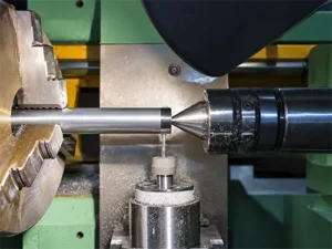
The workpiece diameter is 30 mm, the eccentricity is 0, the axial feed rate is 0.1 mm/r, and the turning-milling method is up-milling;
See Table 3 for other cutting parameters.
The cutting temperature and workpiece surface roughness during the cutting process were measured using a handheld infrared camera and a TR200 surface roughness tester, respectively.
| Experimental Group | Workpiece Rotational Speed (r/min) | Milling Cutter Rotational Speed (r/min) | Cutting Depth (mm) |
|---|---|---|---|
| 1 | 40 | 12,000 | 0.1, 0.2, 0.3, 0.4 |
| 2 | 40 | 6,000, 12,000, 18,000, 24,000 | 0.2 |
| 3 | 20, 40, 60, 80 | 12,000 | 0.2 |
Table 3. Experimental Parameters for Orthogonal Milling of TC11 Titanium Alloy
Figure 2(a) shows the variation in cutting temperature as the milling cutter rotational speed changes;
The cutting temperature increases as the milling cutter rotational speed increases.
In the turning-milling composite machining process, the rotational speed and linear speed of the milling cutter are significantly higher than those of the workpiece;
Therefore, the cutting speed depends on the rotational speed of the milling cutter. We raise the rotational speed of the milling cutter. This lifts the cutting speed.
The contact pressure between the cutting edge and the workpiece cutting layer grows during cutting.
Meanwhile, the workpiece undergoes more plastic deformation each second. Friction between the milling cutter and the chip also becomes stronger.
These changes boost the total heat generated in the cutting zone. Figure 2(b) shows the variation curve of cutting temperature as the workpiece speed changes.
The cutting temperature rises as the workpiece rotational speed increases. The feed rate in turn-mill composite cutting consists of the milling cutter’s axial feed and the workpiece’s tangential feed.
When the milling cutter’s axial feed is constant, an increase in workpiece rotational speed raises the feed rate during the turn-mill process, increasing the cutting volume per unit time.
This leads to an increase in cutting heat generated per unit time, causing the cutting temperature to rise accordingly.
Figure 2(c) shows the curve of cutting temperature versus cutting depth.
Cutting temperature increases as cutting depth increases. We increase the cutting depth. More of the cutting edge participates in cutting.
The contact area between the milling cutter and the chip expands. Friction becomes more severe.
Friction produces more heat. The cutting temperature rises as a result.
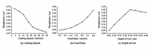
Figure 3(a) shows the effect of the milling cutter speed on the surface roughness of the workpiece;
Surface roughness decreases as the milling cutter speed increases. This is because an increase in the milling cutter speed is equivalent to an increase in the milling-to-workpiece speed ratio.
We raise this ratio. The milling cutter cuts the workpiece surface more frequently. The height of residual surface ridges becomes smaller.
Cutting temperature climbs in the meantime. Higher temperature worsens tearing and adhesion defects on the workpiece surface.
Even so, the workpiece surface roughness tends to decrease overall. Figure 3(b) illustrates the effect of workpiece rotational speed on surface roughness.
Surface roughness increases as the workpiece rotational speed increases.
Increasing the workpiece rotational speed is equivalent to reducing the milling-to-workpiece speed ratio;
We use a smaller speed ratio between the milling cutter and the workpiece. The milling cutter cuts the workpiece surface fewer times.
Residual ridges on the workpiece surface grow higher. Surface roughness rises as a result.
We raise the workpiece rotational speed for comparison. This speeds up the feed motion of the milling cutter.
The cutter removes more material every unit time. Cutting temperature climbs. More surface defects form on the workpiece. The final surface roughness value increases.
Figure 3(c) illustrates the effect of cutting depth on workpiece surface roughness. An increase in cutting depth does not affect the number of cuts the tool makes on the workpiece surface;
Therefore, compared to the milling cutter speed and workpiece rotational speed, the effect of cutting depth on surface roughness is relatively minor.
At the same time, an increase in cutting depth increases the tool’s cutting volume and cutting force, leading to increased vibration and tool wear;
Consequently, surface roughness generally shows an upward trend.
We aim to improve the surface quality of machined titanium alloy parts. We adopt an infrared camera and a roughness tester in this study.
These instruments measure cutting temperature and surface roughness during titanium alloy turn-milling. The main findings are as follows.
(1) The cutting temperature during combined turning and milling of titanium alloys has a significant impact on the machining accuracy of the workpiece surface.
In the combined turning and milling process, cutting temperatures generally increase as cutting parameters increase.
(2) Surface roughness decreases as the milling cutter speed increases, and increases as the workpiece speed and cutting depth increase.
Among these factors, the milling cutter speed and workpiece speed have a greater impact on surface roughness, while cutting depth has a lesser impact.
(3) As a precision machining technique, combined turning and milling can significantly improve the surface quality of titanium alloy components.
Related research can provide technical guidance for the precision machining of titanium alloy components.