How to efficiently machine shaped parts on CNC mill-turn machines?


Precipitation-hardened stainless steel and titanium alloys belong to difficult-to-cut materials. These materials feature high strength, high hardness, low thermal conductivity, and strong work-hardening tendency.
These inherent properties complicate their thread machining. Cutting tools wear quickly during tapping operations. Machining efficiency stays low.
Machined threads also suffer from unsatisfactory surface quality. Small-thread milling serves as an advanced alternative to conventional tapping.
This method achieves high machining accuracy. It accommodates diverse working conditions. The process also generates complex thread profiles.
Therefore, research into small-thread milling methods suitable for difficult-to-machine materials is of great significance.
Currently, machining small threaded holes (less than 6 mm) in difficult-to-machine materials such as titanium alloys, precipitation-hardening stainless steels, and high-strength steels presents significant challenges.
Typically, expensive imported taps are used, and the threading is performed manually by machinists. This often results in taps breaking off inside the workpiece, leading to the scrapping of parts.
Manual tapping carries clear limitations. It yields low productivity, uneven quality and unsatisfactory economic benefits.
These issues turn manual work into a machining bottleneck. Production data supports the analysis of traditional tapping defects. We gathered records for small threaded holes below M6.
The workpieces included precipitation-hardening stainless steel and titanium alloys. We collected all data within a fixed production cycle to visualize existing problems.
As the number of parts processed increased, the scrap rate caused by tap breakage rose sharply.
By the 50th part, the scrap rate for titanium alloy parts reached 15%, while that for precipitation-hardened stainless steel parts reached 10%.
This not only resulted in material waste but also severely impacted production schedules and cost control.
Traditional manual tapping wastes much processing time. One M4 small threaded hole needs 15 minutes for titanium alloy workpieces. The same hole takes 12 minutes for precipitation-hardened stainless steel.
Modern manufacturing sets stricter requirements for production efficiency. This slow method cannot match such rising demands.
Manual tapping quality relies heavily on operator experience and skills.
Different operators produce threads with uneven quality. Such variation weakens the overall stability of finished products.
The production of small threads in difficult-to-machine materials presents significant challenges. Typically, expensive imported taps are used, and the threading is performed manually by machinists.
This method often results in parts being scrapped due to taps breaking off inside the workpiece.
Additionally, manual operations suffer from obvious drawbacks such as low processing efficiency, inconsistent quality, and poor economic returns.
Therefore, finding an efficient and stable threading method has become an urgent issue that needs to be addressed.
Thread milling cutters are classified into single-flute and multi-flute types, each with its own machining advantages.
Single-flute thread milling cutters are suitable for machining threads with different pitches. Single-flute cutters work for thread milling under specific theoretical conditions.
The cutter’s tooth height must exceed the thread pitch. Its cutting edge diameter must stay smaller than the threaded hole diameter.
Both conditions together allow this cutting tool to complete the machining task. While they offer exceptional versatility, their machining efficiency is relatively low;
Multi-flute thread milling cutters can machine multiple threads simultaneously. If the cutting edge length of the cutter exceeds the thread length, the entire thread can be machined with a single helical pass, resulting in higher efficiency;
However, the thread pitch must match the cutter’s pitch.
In both cases, thread milling is achieved through a helical cutting motion within the hole, and the pitch of the helical path must match the thread pitch.
The machining path for thread milling consists of a three-axis interpolated helical path generated by executing G02 or G03 commands. We use a standard right-hand threaded hole to illustrate the tool path.
Programmers can assign clockwise downward helical interpolation to the thread milling cutter. They may also select counterclockwise upward helical interpolation for this operation.
To program a thread milling sequence, one can use CAM software to directly generate the corresponding helical tool path. The drawback of this method is that it relies on software and is not conducive to subsequent adjustments.
The following section focuses on methods for quickly implementing thread milling on different CNC systems.
Thread milling cutters used for small threads generally have poor overall rigidity and are prone to chipping and breakage.
Therefore, in actual use, radial layering should be performed based on the material’s machinability; This is particularly essential for multi-flute thread milling cutters.
To ensure continuous cutting, the thread milling approach and retract movements should follow three-axis synchronized circular arcs.
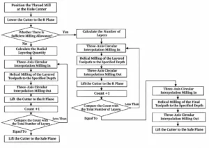
By default, the FANUC CNC system does not include a fixed cycle for thread milling. Therefore, a helical milling macro program suitable for this system was developed.
This program features 14 assignable variables and effectively meets the requirements for thread milling. The execution flow of this thread milling program is shown in Figure 1.
In practical applications, we tracked and recorded the results of using this macro program to machine small threads in precipitation-hardened stainless steel and titanium alloys on FANUC systems.
It was found that for precipitation-hardened stainless steel, the macro program operated stably, and the precision of the machined threads met the requirements.
However, when machining titanium alloys, the high cutting forces associated with these materials caused significant tool wear.
For this reason, we tuned the cutting parameters within the macro program. A reduced feed rate relieves cutting loads. Increased coolant flow enhances heat dissipation.
These adjustments sustain stable machining. They also promote the formation of high-quality threads.
Taking the Sinumerik 810D system as an example, CYCLE90 is the thread milling cycle. This cycle is called as follows:
CYCLE90 (RTP, RFP, SDIS, DP, DPR, DIATH, KDIAM, PIT, FFR, CDIR, TYPTH, CPA, CPO)
The meanings of each parameter are shown in Table 1.
Parameter Name | Description |
|---|---|
RTP | Retract Plane (Absolute) |
RFP | Reference Plane (Absolute) |
SDIS | Safety Distance |
DP | Hole Bottom Depth |
DPR | Drilling Depth Relative to the Reference Plane |
DIATH | Nominal Diameter (External Thread Diameter) |
KDIAM | Core Diameter (Internal Thread Diameter) |
PIT | Thread Pitch |
FFR | Feed Rate for Thread Milling |
CDIR | Thread Milling Direction: 2 = Thread Milling with G2; 3 = Thread Milling with G3 |
TYPTH | Thread Type: 0 = Internal Thread; 1 = External Thread |
CPA | Arc Center, X-Coordinate (Absolute) |
CPO | Arc Center, Y-Coordinate (Absolute) |
Table 1. Description of Each Parameter
CYCLE90 lacks a radial layering function for threads, which can easily cause damage to the thread milling cutter’s tooth profile when machining small threaded holes in difficult-to-machine materials.
Therefore, it cannot be applied directly during actual machining; instead, CYCLE90 should be called multiple times.
For example, to mill an M4 mm thread, with a thread milling cutter cutting width of 0.1, the CYCLE90 command can be called three times: set the DIATH parameter to 3.6 on the first call, to 3.8 on the second, and to 4 on the third.
To better understand the application of CYCLE90 in thread milling within the SIEMENS CNC system, take the milling of an M4 mm thread as an example.
This illustrates how the tool’s cutting path and parameters change when CYCLE90 is called multiple times.
As clearly shown in the figure, as the DIATH parameter changes with each call to CYCLE90, the tool’s cutting path within the hole gradually approaches the final thread dimensions.
Based on a period of trial cutting and the accumulation of actual machining data, it has been determined that certain thread milling cutters can be used to machine difficult-to-machine materials—such as titanium alloys, stainless steel (age-hardened), and high-strength steel—using the cutting parameters shown in Table 2.
Milling Cutter Size | Spindle Speed (rpm) | Feed Rate (mm/min) | Cutting Width (mm) |
|---|---|---|---|
M2 | 4,000–8,000 | 60–130 | >0.05 |
M3 | 4,000–8,000 | 60–130 | >0.07 |
M4 | 3,000–7,000 | 60–130 | >0.06 |
M5 | 3,000–7,000 | 60–140 | >0.13 |
M6 | 2,000–6,000 | 60–150 | >0.15 |
Table 2. Cutting Parameters
Further analysis of the cutting parameters shows that, taking an M4mm thread milling cutter as an example, the feed rate exhibits a certain upward trend as the rotational speed increases;
However, the rate of increase in feed rate varies across different rotational speed ranges.
In actual machining, a reasonable selection must be made within this parameter range based on the specific material and machining requirements.
At the same time, the relationship between cutting width and surface roughness for different milling cutter specifications was analyzed.
As the cutting width increases, surface roughness tends to rise.
This indicates that when pursuing machining efficiency, one should not simply increase the cutting width but must also consider the impact on surface quality.
When machining small threads in difficult-to-machine materials, the magnitude and distribution of cutting forces vary among milling cutters of different sizes.
The magnitude of cutting forces directly affects tool wear, machining accuracy, and machining efficiency.
For milling cutters in the M2–M6 mm range, cutting forces generally increase as the cutter diameter increases.
This is because larger-diameter milling cutters have a longer cutting edge engaged in the cutting process;
Under the same cutting parameters, cutting forces will increase accordingly. For example, an M6 mm milling cutter has a larger diameter than an M2 mm milling cutter;
When machining the same material, the cutting force exerted on the M6 mm milling cutter will be significantly greater than that on the M2 mm milling cutter.
By analyzing the cutting forces of different milling cutter sizes, cutting parameters can be further optimized—such as by appropriately adjusting the feed rate—to balance the cutting forces, reduce tool wear, and improve machining quality.
Thread milling offers significant economic advantages when machining small threads in difficult-to-machine materials.
First, the versatility of thread milling cutters results in relatively lower tool costs.
Single-start thread milling cutters can machine threads of various specifications, reducing the variety and quantity of tools required and thereby lowering tool procurement costs.
Second, because thread milling is highly efficient, the number of qualified parts produced per unit of time increases, thereby improving overall production efficiency.
A batch of small threaded parts from difficult-to-cut materials serves as a typical case. Traditional taps consume hours or even days to finish these threads. This tapping approach also generates a high scrap rate.
In contrast, thread milling can significantly shorten machining time and substantially reduce the scrap rate.
The thread milling method offers inherent advantages over traditional tap threading.
First, the rotational speed of a thread milling cutter is not limited by the pitch, resulting in a much higher cutting line speed compared to a tap, which yields a smoother surface finish on the machined threads;
Second, thread milling cutters offer excellent flexibility. Single-start thread milling cutters support flexible thread production.
One cutter covers multiple thread specifications. It handles different major diameters, pitches and thread tolerances.
This flexibility greatly cuts tool preparation work on site. The method also brings notable economic gains.
Third, thread milling offers good safety during thread machining. Thread milling cutters have a smaller diameter than the threaded pilot hole.
Operators can retrieve a broken cutter from the workpiece quickly. This feature avoids scrapping the whole part after tool breakage.
(1) Selecting the appropriate thread milling cutter is key to machining small threads in difficult-to-machine materials.
The selection should be based on the cutting performance of single-flute and multi-flute thread milling cutters.
(2) To perform thread milling on different CNC systems, it is necessary to master the corresponding programming methods and parameter adjustment techniques.
Both the FANUC and SIEMENS CNC systems offer a wide range of thread milling functions, which can be selected and applied according to actual needs.
(3) Proper selection of thread milling cutting parameters can improve machining efficiency and quality.
Parameters such as spindle speed, feed rate, and cutting width should be optimized based on material properties, tool performance, and machining requirements.