How to efficiently machine shaped parts on CNC mill-turn machines?



Pins and similar components play an indispensable role across various industries.
They are used to connect, support, and facilitate relative motion between parts, offering high connection reliability, excellent stability, superior durability, light weight, ease of machining, and high customizability.
Their importance in various mechanical equipment applications is self-evident.
This paper uses 1Cr17Ni4Cu4Nb as the material of choice.
Taking the machining of a pin shaft product for a specific model, as shown in Figure 1, as an example, this paper introduces methods for ensuring the dimensional accuracy of pin shaft products.
Since this part is produced in batches to some extent and has strict requirements for machining quality, while also necessitating guaranteed production efficiency, it is essential to both enhance part analysis and explore machining processes and methods.
Only in this way can a highly rational and process-optimized production route be planned, and simple, convenient, and reliable specialized fixtures be designed, thereby facilitating the stable and efficient production of this type of part to a certain extent.
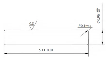
As shown in Figure 1, this product has a small diameter of Φ0.9 mm; the tolerance is +0.006 to –0.002 mm; and the surface roughness is 0.8 μm.
The length tolerance is relatively strict, at (5.1 ± 0.01) mm.
Since the production and machining of this product require multiple clamping operations, cumulative errors may occur during the machining process, affecting the product’s dimensional requirements and quality assurance.
Clamping errors during the production process include fixture errors and clamping errors;
Positioning errors, including positional errors of the product and displacement errors after clamping;
Machining errors, such as force errors between the product and the tool tip during machining;
And measurement errors, including errors in measuring instruments and measurement errors during their use.
Many factors can affect the product’s manufacturing quality.
Therefore, although this pin-type product appears simple and easy to machine, meeting the process dimensional requirements is quite challenging.
Given the structural characteristics of this pin-type product—which features a small shaft diameter and strict dimensional tolerances at the micrometer level—its production and machining are undoubtedly challenging.
The length tolerance requirement is ±0.01 mm. Since this is mass production, high manufacturing efficiency can only be achieved if product quality remains stable, reliable, and consistent.
First, the raw material for these pin-type parts is a polished bar stock with a diameter of Φ3 mm, which requires two clamping operations to complete the manufacturing process.
CNC lathes are primarily used for machining cylindrical parts and are characterized by high precision and a high degree of automation.
Based on the characteristics of the raw material and the structural features of the product, CNC lathes are the preferred choice for the production and machining of these pin-type parts.
The material used for these pin-type products is 1Cr17Ni4Cu4Nb, a high-strength, high-toughness stainless steel that offers good corrosion resistance and high-temperature resistance.
Its machining characteristics include good malleability and formability, indicating that the material has good ductility.
Therefore, cutting tools with high hardness, high toughness, and high wear resistance should be selected for machining to meet the material’s machining requirements.
Selection of Tool Tip: The product has a diameter of Φ0.9 mm and relatively low rigidity; therefore, a tool tip with a radius (R) of 0.15–0.2 mm is selected for machining.
This ensures both the cutting performance of the tool and its rigidity and sharpness during the machining process, thereby guaranteeing the surface roughness and stable dimensional accuracy of the machined product.
Selection of Tool Rake Angle: A larger rake angle increases the tool’s sharpness but reduces its rigidity and wear resistance, making it difficult to guarantee product quality.
Since this material possesses high hardness and toughness and is prone to brittle fracture, a smaller tool rake angle reduces the impact and damage caused by cutting forces on the material, thereby improving machining efficiency and tool life.
However, an excessively small rake angle will lead to a decline in machining quality.
Therefore, an appropriate tool rake angle should be selected to ensure the tool’s rigidity and durability.
The turning process generates a significant amount of cutting heat, which not only affects tool life and the surface finish of the workpiece but also accelerates surface hardening.
Therefore, a coolant with rapid cooling properties should be selected.
The two types of coolants that provide effective cooling are water-soluble coolants and oil-based coolants.
Water-soluble coolants use water as a solvent and are characterized by good fluidity, low viscosity, high volatility, and low cost.
They are primarily suitable for applications requiring high fluidity.
Oil-based coolants use oil as a solvent and are characterized by good heat dissipation, low viscosity, and good corrosion resistance.
They are primarily suitable for applications requiring high heat dissipation.
It can be seen that both types of coolant can meet the cooling requirements for the machining of this product.
In this case, a water-soluble coolant with higher cost-effectiveness is selected to reduce production costs.
Due to the product’s characteristics, it requires two setups to complete the manufacturing process.
First, the first end is machined, including operations such as face turning, external turning, and cutting.
During this process, careful attention must be paid to the selection of cutting tools.
While ensuring tool rigidity and cutting performance, tools with narrower widths and sharp cutting edges should be selected whenever possible.
This ensures that the product is cut cleanly by the tool rather than being snapped due to cutting resistance, which could compromise product quality.
It also lays the groundwork for the machining of the second end.
Next, proceed to the second-end machining: rough-face turning to remove the excess material left from the cutting process → rounding the outer diameter and finishing the face.
Since the product’s outer diameter dimensional tolerance is in the micrometer range, appropriate fixtures must be selected for turning, and clamping force must be moderate.
Excessive clamping force can easily damage the product, leading to poor surface quality and compromising the required outer diameter dimensions.
Conversely, insufficient clamping force can cause the product to shift during turning as the tool tip gradually wears down, increasing friction between the tool and the workpiece.
This displacement compromises both surface quality and dimensional accuracy.
Since the radius (R) of the turning tool’s cutting edge is similar to the product’s shaft diameter, significant cutting resistance is generated during turning.
This resistance increases as the cutting edge becomes blunter, making it easy for the product to shift during machining, which can scratch the surface and cause bending deformation of the shaft.
Consequently, the product’s length dimensions cannot be consistently guaranteed, resulting in a high scrap rate, low efficiency, and unstable product quality.
To prevent surface scratches, bending deformation, and dimensional inconsistencies caused by variations in clamping force and cutting resistance, a specialized fixture has been proposed to address these issues.
To address quality issues during the machining process of this product, the fixture was designed to prevent both surface scratches and bending deformation.
Additionally, the fixture must ensure stable and reliable product quality and high machining efficiency.
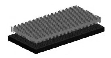
Therefore, a flat-plate fixture with a transition fit to the product was adopted.
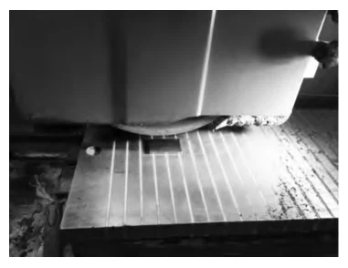
By utilizing the fit between the product and the fixture, the second end of the product is machined using a planar grinding method.
During operation, the product is placed into the flat-plate fixture with a transitional fit and secured to the worktable for grinding.
The fixture is designed as a flat plate with a small hole machined into it to accommodate the product’s shaft diameter with a transitional fit.
The height of the hole matches the finished length of the product.
The fixture is then secured to the worktable for layer-by-layer grinding.
The exploded view is shown in Figure 2, and the flat grinding process is illustrated in Figure 3.
Based on the above analysis, research, and practical validation, and taking into account the product’s specific characteristics and dimensional requirements, we have established a rational machining sequence and selected appropriate cutting tools.
We have also designed a relatively simple, stable, and reliable fixture.
This method consistently maintains reliable product quality during the machining of pin-type components.
It also streamlines production operations, improves manufacturing efficiency, and supports stable, high-efficiency production while providing a strong foundation for machining similar products in the future.

