How to efficiently machine shaped parts on CNC mill-turn machines?



Aerospace products widely use cylindrical parts, primarily as components of actuation systems.
They are found in various applications, including door actuation systems and landing gear systems.
Since cylindrical parts require a moving fit between the inner bore and the outer diameter of the piston rod, the inner bore must meet very strict specifications.
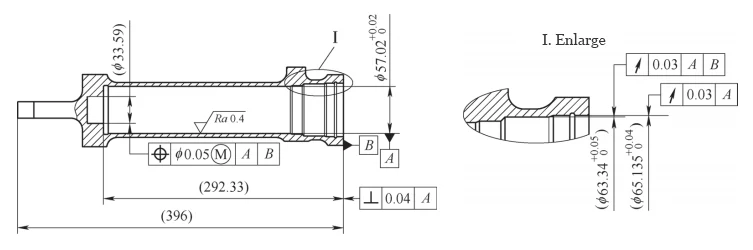
A cylindrical part manufactured by our company is shown in Figure 1.
The raw material is 7050 aluminum alloy, with a bore diameter tolerance of 0.02 mm, an inner bore surface roughness value of Ra = 0.4 μm, and an inner bore depth of 292.33 mm.
The inner bore serves as design datum A, and the bore opening and end faces have associated geometric and positional requirements relative to the inner bore.
This part presents three machining challenges:
① The bore has a tight diameter tolerance, making it difficult to control this dimension and achieve stable mass production.
② The surface roughness of the inner bore is Ra = 0.4 μm, which is a very stringent requirement.
③ The inner bore serves as the design datum; the radial runout of the bore opening relative to this datum is 0.03 mm, and the perpendicularity of the end face relative to the axis of the inner bore is 0.04 mm, both of which are high-precision requirements.
To meet the above machining requirements, the original process utilized a honing machine to machine the inner bore.
Honing is an effective method for finishing inner bores; its principle involves using an expandable honing head to press the honing stones against the workpiece surface, thereby achieving high inner bore precision and surface quality.
The original process utilized a Shanneng vertical honing machine, equipped with a matching honing head and honing stones, enabling batch production.
However, due to the large volume of parts processed on the honing equipment and the extended processing time, the required honing capacity far exceeded what the equipment could provide, impacting part output and delivery.
To address this situation, the engineering team decided to improve the machining process for the inner bore of this part.
After analyzing the machining requirements for the part’s internal bore, analysis shows that a CNC lathe can bore the part’s internal bore.
Both the stability of part clamping and the stability of the cutting tools affect the quality of internal bore machining.
The first issue to address is part clamping. Since this part is thin-walled, with a wall thickness of only 4.8 mm, it is prone to deformation during clamping.
During honing, the process clamps the part axially without clamping the outer circumference, eliminating the risk of deformation.
When boring the inner hole on a lathe, the process clamps the part only by its outer circumference, which necessitates the design of a specialized fixture.
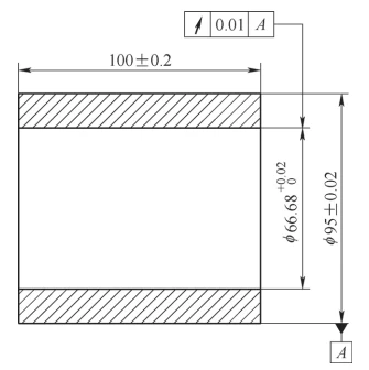
(1) Clamping the part using a sleeve: Based on the part’s clamping requirements, engineers designed a specialized sleeve, with its dimensions and structure shown in Figure 2.
After machining, the sleeve is cut open from the center. After the sleeve was cut open, deformation occurred in its inner bore, with a deformation of 0.5 mm.
This prevented it from fitting snugly against the part’s outer diameter.
When clamping the part, the setup caused significant runout, and the deformation of the inner bore exceeded machining requirements.
To address this issue, the team machined multiple sets of sleeves (see Figure 3).
However, since the deformation patterns after cutting remained unpredictable, the sleeve-based clamping plan failed.

(2) Clamping the workpiece with soft jaws: After analyzing the workpiece structure, the process uses soft jaws for clamping.
Measures were taken, such as moving the clamping position backward, reducing the clamping pressure of the self-centering chuck, and decreasing the cutting depth, to eliminate workpiece deformation caused by clamping and ensure that the workpiece would not loosen during machining.
The clamping configuration of the part is shown in Figure 4.
Through testing, the team reduced the clamping pressure of the self-centering chuck from 4.0 MPa to 2.4 MPa, meeting the clamping requirements.
(3) Boring with Anti-Vibration Tools: Achieving a bore diameter tolerance of 0.02 mm through boring requires high machining stability and presents significant challenges.
Ultimately, the engineering team selected anti-vibration boring tool holders and cutting heads from Sandvik Coromant. The anti-vibration boring tools used for the internal bore are shown in Figure 5.


During boring tests, the process produced inconsistencies in hole diameter between the hole opening and the bottom.
The primary cause was tool deflection of the anti-vibration tool holder during the boring process.
By setting a 0.05 mm taper in the internal boring program, the process resolved the issue of inconsistent hole diameter, ensuring the dimensional stability of the internal bore.
The internal bore of the part requires a surface roughness value of Ra = 0.4 μm, which is easily achieved through honing but difficult to achieve through boring.
To address this, the engineering team tested multiple sets of parameters, successfully resolving the issue of internal bore surface roughness.
Ultimately, the engineering team selected a 35°-angle cutting tool with a tool tip radius of R0.2 mm for machining.
After testing multiple sets of parameters, the surface roughness value Ra of the internal bore could be consistently controlled below 0.4 μm, enabling mass production.
The internal bore surface roughness parameters and inspection results are shown in Table 1.
| Parameter | Description | Measurement Result (μm) |
|---|---|---|
| Ra | Arithmetic Mean Roughness Deviation | 0.1065 |
| Rp | Maximum Profile Peak Height | 0.3611 |
| Rt | Total Profile Height | 1.0202 |
| Rz | Maximum Height of the Profile | 0.8074 |
Table 1. Internal Bore Surface Roughness Parameters and Measurement Results (Unit: μm)
There are two primary geometric tolerances for the part: a radial runout of 0.03 mm for the φ65.135 mm bore relative to datum A, and a perpendicularity of 0.04 mm for the part’s end face relative to datum A.
To ensure these geometric tolerances, the process must first control clamping deformation to prevent the machining process from compromising the requirements established in previous processes;
Second, the process design must establish a scientifically sound process flow to ensure machining stability.
Using a self-centering chuck to clamp the part ensures compliance with the process requirements for CNC turning, and the process plan requires improvement based on the part’s machining requirements.
The improved process flow can meet the stability requirements for part machining and specifically includes the following steps:
1) Rough-turn the outer diameter on a CNC lathe to serve as the reference for subsequent machining.
2) Drill the inner bore using a deep-hole drill.
3) Using the outer diameter as a reference, bore the end face, additional outer diameter, and center hole on a CNC lathe, ensuring coaxiality within 0.02 mm.
4) Mill the part’s outer contour on a four-axis milling machine.
5) Clamp the additional outer diameter, secure the reference outer diameter with a center support, and bore the φ65.135 mm inner hole and the initial A-reference hole on a CNC lathe, ensuring the radial runout of the initial hole is within 0.02 mm, and bore the end face.
The CNC lathe machining operations are shown in Figure 6.

(6) Flip the part, clamp it by the outer diameter turned in the previous operation, and position the tailstock against the added center hole.
Use the CNC lathe to turn an outer diameter of φ(66.64±0.05) mm, controlling the coaxiality between the inner bore and the outer diameter to within 0.03 mm.
The φ(66.64±0.05) mm outer diameter machined in this process serves as the same outer diameter used for clamping when turning replaces honing.
Through process improvements, boring the inner bore using a CNC lathe can meet the requirements for bore dimensions, surface roughness, and geometric tolerances.
Currently, the manufacturing process produces this part reliably in batches, achieving a 100% product yield rate.
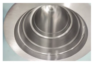
Figure 7 shows the surface condition of the part’s internal bore after CNC lathe boring, which achieves a smooth, mirror-like finish.
The “turning instead of honing” process improvement has overcome the bottleneck of honing operations, facilitated mass production of the part, and ensured timely delivery.
This study focused on process improvements for the precision machining of internal bores in large cylindrical parts.
Starting from three key machining challenges associated with these internal bores, the engineering team adopted an innovative “turning-instead-of-honing” method to address each issue systematically.
By integrating on-site trial results, the engineering team optimized the process flow and successfully implemented the proposed process improvement measures.
This process improvement resolved the high costs, long lead times, and insufficient production capacity associated with honing.
The breakthrough in using CNC lathes to replace honing machines for the precision machining of internal bores has improved part manufacturability, reduced processing costs, and shortened the manufacturing cycle.

