How to efficiently machine shaped parts on CNC mill-turn machines?



As a seasoned mechanical designer, you’ve reviewed countless drawings and overseen countless machining processes. When we talk about “geometric tolerances,” it’s a specialized field that encompasses both theory and practice—how well do you understand it?
In production and mechanical design, misunderstanding geometric tolerances may create discrepancies.
Such inconsistencies can emerge between design drawings and actual machining analyses or finished results.
In the worst cases, this issue can trigger serious consequences.
Today, let’s take a systematic look at the 14 geometric tolerance symbols.
First, here’s the key point: the table below lists the 14 internationally standardized symbols for form and position tolerances—this is very important.
| Tolerance Type | Category | Feature | Symbol | Datum Required |
|---|---|---|---|---|
| Form Tolerances | Form | Straightness | — | No |
| Flatness | ▱ | No | ||
| Circularity (Roundness) | ○ | No | ||
| Cylindricity | ⌭ | No | ||
| Profile Tolerances | Profile | Profile of a Line | ⌒ | Yes or No |
| Profile of a Surface | ⌓ | Yes or No | ||
| Position Tolerances | Orientation | Parallelism | ∥ | Yes |
| Perpendicularity | ⊥ | Yes | ||
| Angularity | ∠ | Yes | ||
| Position | Position | ⌖ | Yes or No | |
| Concentricity (Coaxiality) | ◎ | Yes | ||
| Symmetry | ≡ | Yes | ||
| Runout | Circular Runout | ↗ | Yes | |
| Total Runout | ⟲ | Yes |
Shape tolerance
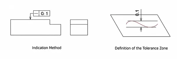
Straightness belongs to one category of geometric tolerances.
It serves to control the geometric error of actual straight features on a part.
Typical examples include surface generatrices and axes. These features are evaluated against an ideal straight line.
It is commonly referred to as the degree of straightness and indicates the extent to which the actual shape of a part’s straight features conforms to the ideal straight line.
The straightness tolerance is the maximum allowable deviation of the actual line from the ideal straight line.
Legend Explanation 1: Within a given plane, the tolerance zone must lie within the area between two parallel straight lines spaced 0.1 mm apart.
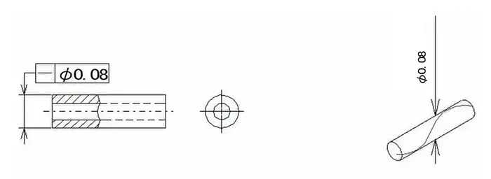
Legend Explanation 2: If the symbol Φ is placed before the tolerance value, the tolerance zone must be within the area defined by a cylindrical surface with a diameter of 0.08 mm.
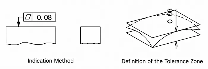
Flatness limits the degree of undulation on a surface; the tolerance zone is the space between two parallel planes.
The term “flatness,” as commonly used, refers to the actual shape of a part’s planar features and how closely they conform to an ideal plane.
The flatness tolerance is the maximum allowable deviation of the actual surface from the ideal plane.
Legend: The tolerance zone is the area between two parallel planes spaced 0.08 mm apart.
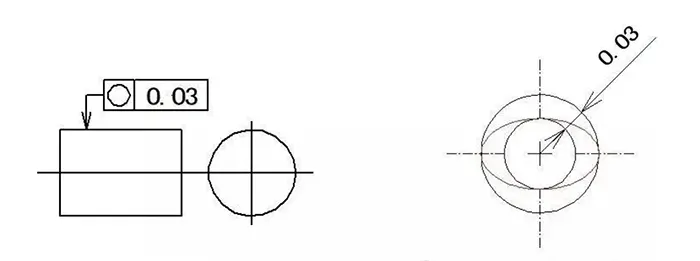
Roundness defines the degree to which the cross-sectional profile of a circle approximates a perfect circle.
The tolerance zone is the annular region between two concentric circles in the same plane.
Commonly referred to as “circularity,” it describes the condition in which the actual shape of the circular features on a part remains equidistant from its center.
The roundness tolerance is the maximum allowable deviation of the actual circle from the ideal circle on the same cross-section.
Legend: The tolerance zone must be located on the same cross-section and defined as the area between two concentric circles with a radius difference of 0.03 mm.
Cylindricity is a comprehensive specification that defines the shape of an entire cylindrical surface (including roundness, straightness, etc.).
The tolerance zone forms a tubular region bounded by two coaxial cylindrical surfaces.
It describes a condition in which all points on the outer contour of the part’s cylindrical surface keep an equal distance from its axis.
The cylindricity tolerance is the maximum allowable deviation of the actual cylindrical surface from the ideal cylindrical surface.
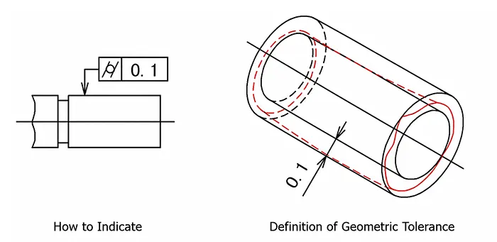
Legend: The tolerance zone is the area between two coaxial cylindrical surfaces with a radius difference of 0.1 mm.
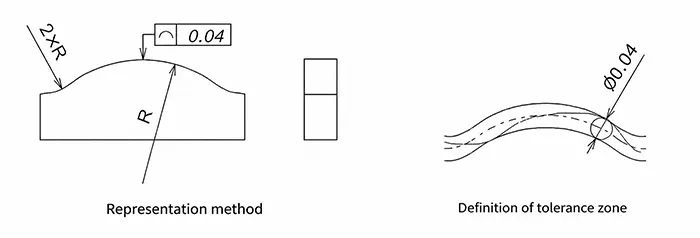
Line profile limits the shape deviation of any curve.
The tolerance zone refers to the area between two enveloping lines.
These two lines are equidistant on either side of the theoretical profile line.
It defines a condition in which a curve of any shape retains its ideal form on a specified plane of the part.
The line profile tolerance refers to the allowable variation of the actual profile line of a non-circular curve.
Legend: The tolerance zone is the area between two envelopes that enclose a series of circles with a diameter of 0.04 mm.
The centers of these circles lie on a line with the theoretically correct geometric shape.
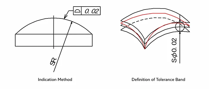
Surface profile limits the shape deviation of any curved surface.
The tolerance zone is the area between two enveloping surfaces.
These surfaces are located at equal distances on either side of the theoretical profile surface.
It represents the condition in which any curved surface on a part maintains its ideal shape.
The surface profile tolerance refers to the allowable variation of the actual contour line of a non-circular surface relative to the ideal profile surface.
Illustration Explanation:
The tolerance zone is defined by the area between two enveloping lines that enclose a series of spheres with a diameter of 0.02 mm;
The centers of these spheres are theoretically located on the surface of the correct geometric shape.
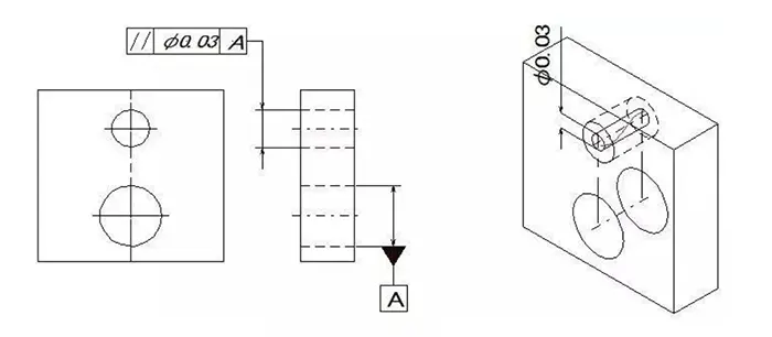
Parallelism limits the deviation of the measured feature from remaining parallel to the reference.
The tolerance zone lies within two parallel planes or a parallel cylinder that are parallel to the reference;
In other words, it refers to the degree of parallelism maintained.
It describes the condition where the actual measured feature on a part stays at an equal distance from the reference.
The parallelism tolerance is the maximum allowable variation between the actual orientation of the measured feature and the ideal orientation parallel to the reference.
Legend: If the symbol Φ is prefixed to the tolerance value, the tolerance zone is defined as the interior of a cylindrical surface with a diameter of Φ0.03 mm parallel to the reference.
Perpendicularity limits the deviation of a measured feature from being perpendicular to a reference.
The tolerance zone lies within two parallel planes or a cylindrical surface perpendicular to the reference;
That is, it refers to the degree to which two features remain orthogonal to each other.
It means the measured feature on a part maintains a correct 90° angle relative to the reference feature.
The perpendicularity tolerance defines the maximum allowable deviation.
This deviation exists between the actual orientation of the measured feature and the ideal orientation perpendicular to the reference.
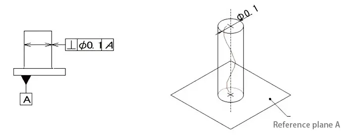
Legend Explanation 1: If the symbol Φ is placed before the tolerance value, the tolerance zone is enclosed within a cylindrical surface.
The cylinder has a diameter of 0.1 mm and is perpendicular to the reference surface.
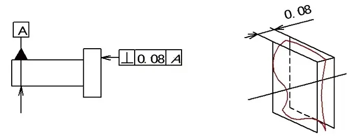
Legend Explanation 2: The tolerance zone must be located between two parallel planes that are 0.08 mm apart and perpendicular to the reference line.
Slant limits the deviation of the feature being measured from maintaining a specified angle (other than 0° or 90°) relative to the reference.
The tolerance zone is the area between two parallel planes.
These planes form a specified angle with the reference. It represents the proper condition where two features on a part maintain any specified relative angle.
The slant tolerance defines the maximum allowable variation.
This variation exists between the actual orientation of the measured feature and its ideal orientation.
The ideal orientation forms a specified angle relative to the reference.
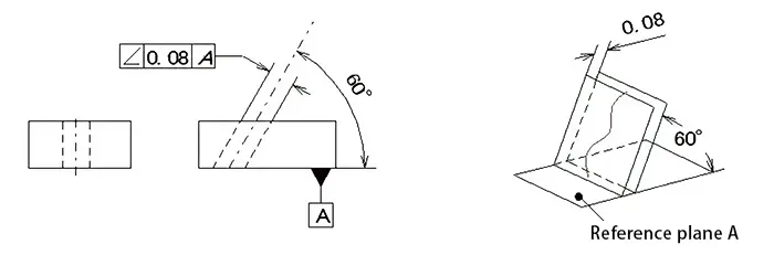
Legend Explanation 1: The tolerance zone for the measured axis lies between two parallel planes.
The spacing between the two planes is 0.08 mm, and they form a theoretical angle of 60° with reference plane A.
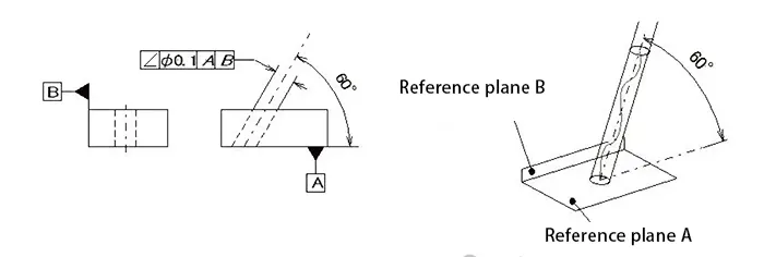
Legend Explanation 2: If the symbol Φ is placed before the tolerance value, the tolerance zone must lie within a cylindrical surface with a diameter of 0.1 mm.
This tolerance zone should be parallel to plane B, which is perpendicular to reference A, and form a theoretically correct angle of 60° with reference A.
Position refers to the degree to which points, lines, and planes deviate from their ideal positions.
Depending on the object, the tolerance zone can be a circle, a sphere, two parallel planes, two parallel lines, or a cylinder, with its center or axis located at the ideal position.
It indicates the accuracy of elements such as points, lines, and planes on a part relative to their ideal positions.
Positional tolerance is the maximum allowable variation of the actual position of the measured feature relative to its ideal position.
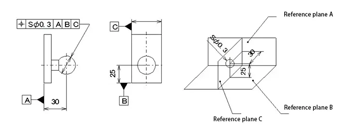
Legend: When the symbol SΦ precedes the tolerance zone, the tolerance zone is the area inside a sphere with a diameter of 0.3 mm.
The center point of the spherical tolerance zone corresponds to the theoretically correct dimensions relative to reference points A, B, and C.
Coaxiality limits the degree to which the measured axis deviates from the reference axis.
The tolerance zone is the interior of a cylinder in which the measured axis coincides with the reference axis;
This is commonly referred to as the degree of coaxiality, indicating the condition in which the measured axis on a part remains aligned with the reference axis.
The coaxiality tolerance is the allowable variation of the actual measured axis relative to the reference axis.
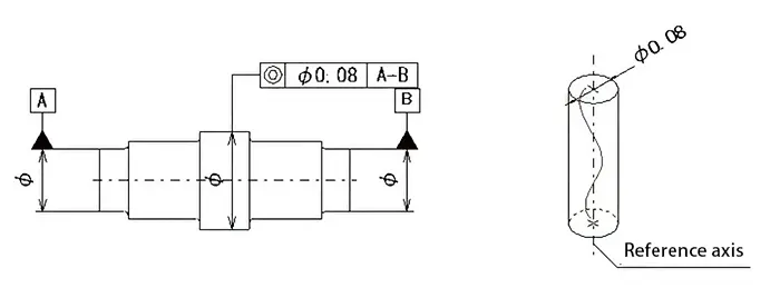
Legend: When a tolerance value is indicated, the tolerance zone is the area between two cylinders with a diameter of 0.08 mm.
The axis of the circular tolerance zone coincides with the reference axis.
Symmetry limits the degree to which a measured central feature (such as the center plane of a keyway) deviates from a reference central feature.
The tolerance zone is the region between two parallel planes. These planes are symmetrically distributed relative to the reference center.
It indicates that the two symmetrical central features on the part stay within the same central plane.
The symmetry tolerance is the allowable variation of the actual feature’s symmetrical center plane (or centerline, axis) relative to the ideal symmetrical plane.
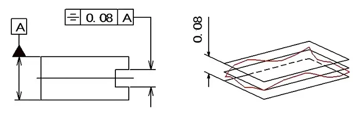
Legend: The tolerance zone is the area between two parallel planes or straight lines that are 0.08 mm apart and symmetrically arranged relative to the reference center plane or centerline.
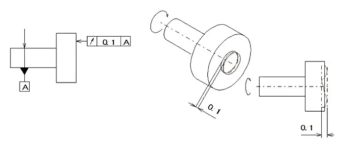
Circular runout refers to the amount of runout at a specific cross-section or position as a part rotates through one full revolution.
Radial: Within the same cross-section, between two concentric circles whose centers lie on the reference axis.
End face: Between two circles on the same cylindrical surface along the generatrix.
This represents the condition where the rotational surface of the part maintains a fixed position relative to the reference axis within a specified measurement plane.
The circular runout tolerance represents the maximum allowable variation within a specified measurement range.
This condition occurs when the measured actual feature rotates a full circle around the reference axis without axial movement.
Legend Explanation 1: The tolerance zone is the area between two concentric circles.
The circles are perpendicular to any measuring plane and have a radius difference of 0.1 mm. Their centers are located on the same reference axis.
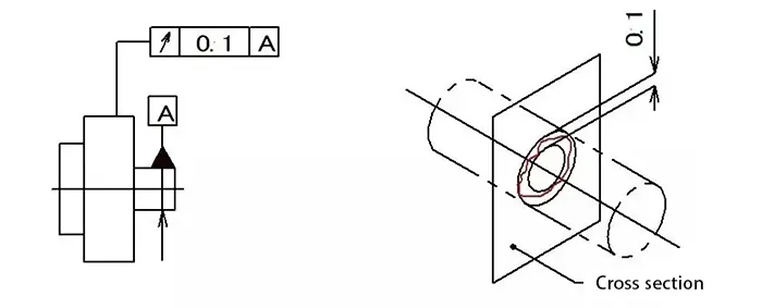
Legend Explanation 2: The tolerance zone is the area between two circles.
Each circle has a radial separation of 0.1 mm. They lie on the cylindrical measuring surface at any radial position and share the same axis as the reference.
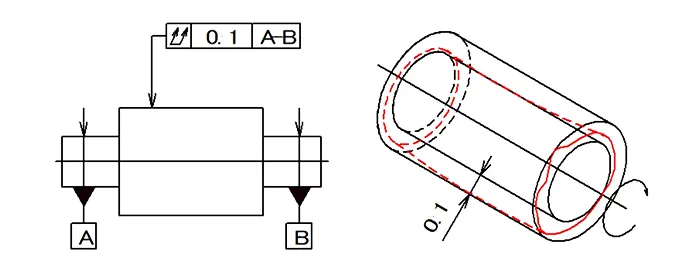
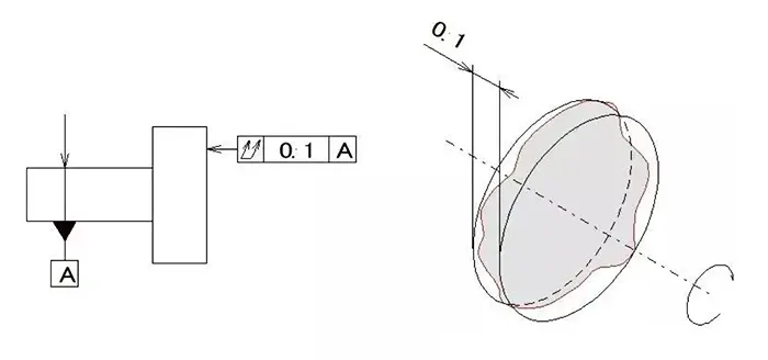
Total runout refers to the runout of the entire surface of a part during continuous rotation.
Radial: Between two cylindrical surfaces that are coaxial with the reference axis.
Facial: Between two parallel planes perpendicular to the reference axis.
This refers to the runout along the entire measured surface when the part rotates continuously about the reference axis.
The total runout tolerance is the maximum allowable runout when the measured feature rotates continuously about the reference axis while the indicator moves relative to its ideal contour.
Legend Explanation 1: The tolerance zone is the area between two cylindrical surfaces that are coaxial with the reference axis and separated by a radial difference of 0.1 mm.
Legend Explanation 2: The tolerance zone is the area between two parallel planes that are perpendicular to the reference line and separated by a distance equal to the radius difference of 0.1 mm.
Geometric tolerances are fundamental to achieving precision, consistency, and functional reliability in mechanical design and machining.
The 14 standardized geometric tolerance symbols provide a systematic way to control the form, profile, orientation, position, and runout of manufactured features.
Each tolerance addresses a specific aspect of geometric accuracy. Form tolerances control the basic shape of individual features without requiring a datum. Profile tolerances control the contour of lines and surfaces.
Orientation tolerances establish angular relationships between features and datums, while position tolerances control the location and symmetry of features.
Runout tolerances ensure stable rotational accuracy relative to a reference axis.
Understanding these symbols goes far beyond simply recognizing their shapes.
Engineers and machinists must understand the corresponding tolerance zones, datum references, measurement methods, and functional requirements.
A small misunderstanding in a drawing can lead to incorrect machining strategies, inappropriate inspection methods, assembly problems, increased production costs, or even premature component failure.
Therefore, mastering geometric tolerances requires combining theoretical knowledge with practical experience in design, machining, measurement, and quality control.
When designers, manufacturers, and inspectors interpret GD&T requirements consistently, drawings become a precise communication tool that connects design intent with actual manufacturing results.
Ultimately, correct application of geometric tolerances helps ensure that mechanical parts not only meet dimensional requirements but also perform reliably in real-world applications.

