How to efficiently machine shaped parts on CNC mill-turn machines?



In the field of CNC lathes, the term “slant bed” is quite familiar. But does seeing a machine with a slanted appearance really mean it’s a slant-bed lathe? Not necessarily.
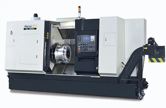
A true slant bed is about more than just the slanted outer casing.
At its core lies the integrated slanted design of the bed itself, the guideway layout, the slide structure, and the cutting force transmission path.
This design allows chips to fall naturally and more easily, reducing buildup;
At the same time, it shortens the force transmission path, enhancing the machine tool’s overall rigidity and machining stability, while also creating better spatial conditions for automatic chip removal and robotic loading/unloading.

However, some so-called “inclined bed” machines simply feature an inclined exterior design, while the internal structure remains a traditional flat bed.
They may look inclined on the outside, but at their core, they are not.
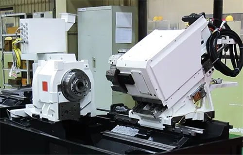
Therefore, when determining whether a machine tool is a true slant-bed machine, one cannot rely solely on its appearance, much less on a single photo in a brochure.
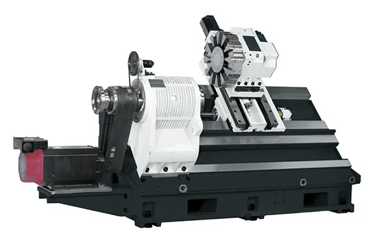
Those who truly understand machine tools will examine:
The technical sophistication of a machine tool is often hidden in places invisible to the user.
The difference between a genuine and a fake slant bed lies not in “how aesthetically pleasing the slant is,” but in “whether the slant serves a purpose.”
In fact, its structure, not its appearance, first and foremost defines a true slant‑bed machine tool.
Some machine tools merely feature a slanted outer casing, while the internal bed, guideways, and load-bearing structures remain those of a traditional flat-bed machine.
Such “slant-bed” machines are largely just a stylistic variation.
A true slant-bed machine tool features a bed, guideways, saddle, and tool turret that collectively form a rational inclined structure.
Common angles include 30°, 45°, and 60°.
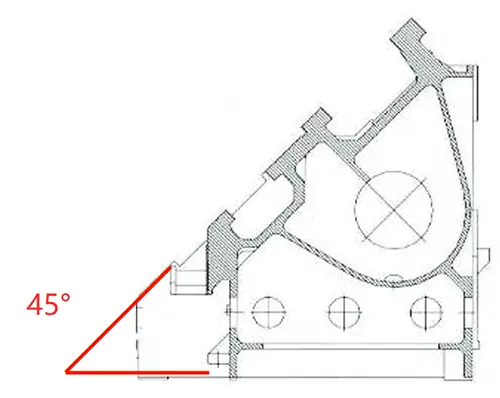
So, does a larger angle mean better performance? Not necessarily.
A 30° angle is relatively gentle and typically provides a larger effective machining space and a better range of tool movement.
Given the same machine tool dimensions, a 30° configuration generally offers more favorable machining space for large-diameter workpieces, and interference issues between the tool turret and the workpiece are relatively easier to control.
At the same time, however, the bed’s support and transmission of cutting forces require larger structural dimensions to ensure rigidity.
45° is a classic angle adopted by many CNC lathes. It strikes a good balance between chip evacuation, rigidity, machining space, and tool interference.
The guideways and bed form a reasonably optimized load‑bearing relationship, allowing cutting forces to be transmitted directly to the bed while ensuring ample tool clearance.
Therefore, the 45° angle is not chosen simply because it “looks the best,” but rather as a mature solution developed through extensive engineering practice.
The 60° slant bed features a steeper angle, and one of its key advantages is the ability to create a more compact structure with a lower center of gravity.
This structure offers significant advantages for machining scenarios involving heavy cutting and high rigidity requirements.
However, a larger angle also means more complex spatial relationships between components such as the tool turret, cutting tools, workpieces, and the tailstock.
If the design is not well-executed, issues such as tool interference and a reduction in the effective machining diameter may arise.
Therefore, a 60° angle does not necessarily mean it is better than a 45° angle, just as a 45° angle is not necessarily better than a 30° angle.
What really matters is:
Whether this angle is appropriate given your machining diameter, turret size, spindle center height, and cutting load.
So, what is the “interference diameter”?
Simply put, it is the maximum allowable machining space boundary formed between moving components—such as the turret, cutting tools, and slide—and the workpiece during actual operation.
Even for machine tools with the same nominal Φ500 specification, the actual maximum machinable diameter can vary significantly depending on the bed angle, guideway position, and turret configuration.
Therefore, when reviewing machine tool specifications, don’t just look at the “maximum swivel diameter.”
Instead, you should ask:
These are the truly valuable parameters.
What is the true essence of an inclined-bed machine tool?
It’s not whether the bed angle is 30°, 45°, or 60°.
Rather, it’s the comprehensive balance between structural rigidity, force transmission paths, guideway layout, machining space, and chip evacuation capacity.
A truly excellent slant-bed machine tool should achieve the following:
And there is no interference with large-diameter workpieces.
So, the next time you see a “slant-bed” machine tool, don’t just focus on how aesthetically pleasing the slant is.
A true slant‑bed machine tool features a slanted structure; true rigidity is embedded within that structure.

