How to efficiently machine shaped parts on CNC mill-turn machines?


Thin-walled bracket-type parts are made of 2A12-T4 aluminum alloy (in accordance with GB/T 3880.1—2023). This material has low hardness and high ductility, making it prone to tool sticking during machining;
It also has a high coefficient of thermal expansion and is sensitive to temperature changes;
Furthermore, due to factors such as cutting forces during machining, it is prone to machining deformation.
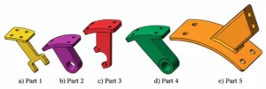
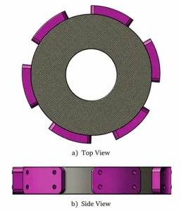
The structure of thin-walled aluminum alloy bracket-type parts is shown in Figure 1.
These parts come in a variety of specifications and dimensions, all featuring irregularly shaped bracket structures with fan-shaped, circular arc surfaces and connecting rib plates of varying wall thicknesses.
Designers set the radius of the circular arc surfaces to mate with the structural components they support, so these surfaces require high machining precision.
Workers must machine locating holes on the circular arc surfaces and the connecting rib plates of these parts to act as connection and fastening points.
The wall thickness of the curved surfaces is relatively thin, ranging from 3 to 5 mm, while the rib plate thickness ranges from 5 to 14 mm, with a thickness tolerance of 0.1 mm.
The dimensional tolerance for the clamping alignment holes machined on the curved surfaces and the alignment holes on the rib plates is 0.05 mm.
Manufacturers originally machined thin-walled bracket-type parts using CNC milling. Several factors affect the machining outcome.
These factors cover how well the machining method fits the process and whether the machining plan is reasonable.
Cutting forces, clamping forces, and material residual internal stresses interact together.
This interaction easily deforms the parts. The deformation creates major difficulties for machining.
The manufacturing sequence for Parts 1 through 4 shown in Figure 1 is as follows: turning → marking → milling on a four-axis machining center → cutting off on a conventional horizontal milling machine → full-contour milling on a machining center → finishing by a machinist.
This process suffers from issues such as significant machining deformation, low material utilization, and low machining efficiency.
Taking Part 2 in Figure 1 as an example, operators turn the part blank.
They define the blank’s outer diameter, inner bore, and thickness according to the arc radius and rib dimensions of thin-walled bracket-type parts.
Next, operators mount the blank on an indexing head. A high-precision vernier caliper marks contour lines and aligns auxiliary reference lines on the blank surface.
A four-axis machining center paired with a dedicated fixture fixes the workpiece and aligns the auxiliary reference lines.
The machine then mills the sector curved surface and drills positioning holes (see Figure 2).
On a conventional horizontal milling machine, clamping plates hold the workpiece.
A serrated end mill cuts and separates individual workpieces.
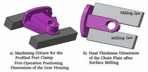
Operators fit the workpiece into a copy clamp and machine the contour features and locating holes on the first side of the rib plate to meet drawing specifications.
Workpieces are flipped and re-clamped afterward. Machining proceeds to reach the final rib plate thickness (see Figure 3).
A machinist removes burrs and rounds the edges.
The manufacturing process for Part 5 shown in Figure 1 is as follows: turning → full-contour milling on a machining center → drilling of drilling pilot holes and scribing → milling to break off → setting arc lengths on a machining center → finishing by a machinist.
Machining starts with turning the part blank. Designers use the arc radius and rib sizes of thin-walled bracket parts for dimension definition.
They set the blank’s inner bore to the finished size. The blank outer diameter retains allowance for subsequent milling. Designers machine the blank thickness directly to its final dimension.
Mount the fixture on a four-axis machining center, place the workpiece into the fixture, fit the clamping cover, and secure it with nuts.
Machine the workpiece’s outer contour and positioning holes, and use a marking tool to score lines to facilitate subsequent machining.
The full contour milling of Part 5 on the machining center is shown in Figure 4.
Using a standard horizontal milling machine, cut the workpiece along the marked lines with a saw-tooth milling cutter.
On the machining center, clamp the workpiece by its rib section using a face vise to machine the various dimensions of the curved surfaces;
A fitter will subsequently finish the various sections of the workpiece.
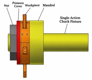
Engineers designed a fully open, internally expanding elastic fixture to efficiently machine a wide range of bracket-type parts in various sizes.
The fixture is made of 60Si2Mn spring steel, with a quenched hardness of 45–50 HRC.
We optimized the quenching cooling method and performed thorough stress-relief tempering on the fixture.
After quenching, we stress-relief temper the fixtures at 260–280 °C.
Next, we perform shape-setting tempering at 360–380 °C. An auxiliary stabilization aging treatment follows this process.
This extra step eliminates residual machining stresses. It sustains consistent dimensional accuracy and reliable clamping performance.
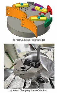
Figure 5 shows the fully open, internally expandable elastic fixture clamping a bracket-type workpiece.
We consider the machining features of thin-walled bracket parts across different sizes.
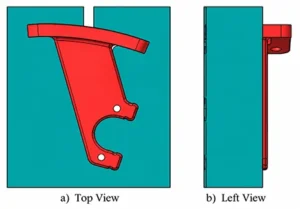
Figure 1 displays five sample components, labeled Part 1 to Part 5. A precision drilling fixture secures these parts for hole positioning.
This setup supports the full machining of all locating holes. This fixture features a simple structure, convenient clamping, and excellent performance, thereby optimizing the machining process.
Figure 6 illustrates the clamping setup for precision drilling of locating holes in thin-walled bracket-type parts.
The improved process route is as follows: sheet metal blanking → EDM wire cutting for full-contour machining → low-temperature stress-relief aging treatment → CNC precision milling to ensure rib thickness dimensions → precision drilling and reaming of positioning holes on a four-axis machining center.
The new process differs from the original version. It introduces wire cutting and aging treatment.
It removes manual machining work. These changes deliver consistent parts and stable dimensions.
The overall process flow is sound, with high machining accuracy, and has achieved the objectives set at the project’s inception.
1) The design of specialized tooling resolved issues inherent in traditional processes, such as severe machining deformation, high dimensional tolerance deviation rates, and low production efficiency.
The fully open, internally expanding elastic fixture employs a contour-following design combined with an elastic opening structure to ensure uniform clamping of the workpiece and prevent localized stress concentration.
We designed a precision drilling fixture for locating holes in thin-walled bracket-type parts;
By utilizing formed locating surfaces to construct a versatile contour-following locating structure, this fixture enables the rapid clamping of thin-walled bracket-type parts of various specifications.
This has significantly improved production efficiency, simplified the process flow, and offers superior scalability for mass production.
2) Compared to the original process, the optimized process route adds wire-cut EDM and aging treatment steps, effectively redistributing the rough machining tasks previously handled by the machining center.
This fully leverages the advantage of wire-cut EDM—which causes minimal deformation during contour machining—and significantly reduces machining deformation.
It breaks away from the traditional approach of relying entirely on milling machines for the rough machining of thin-walled bracket-type parts.
The introduction of the wire-cut EDM process improves material utilization and effectively resolves deformation issues caused by stress accumulation during rough machining.
Manual machining operations have been eliminated.
The overall process flow is well-designed, effectively ensuring part consistency and dimensional stability, while delivering high machining efficiency and reducing manufacturing costs.
3) By optimizing the machining parameters for thin-walled bracket-type parts and using software to automatically generate optimized toolpaths, overall machining efficiency has been improved by 20% compared to the original process.
The machining method for various thin-walled aluminum alloy bracket-type parts has been successfully applied to the production of a specific product at our company, yielding significant results.
We deploy dedicated tooling and fixtures alongside precision drilling jigs for locating holes.
We also apply optimized process sequences, proper clamping strategies and refined machining techniques.
These measures enable fast clamping and batch production of bracket parts with diverse specifications.
Field tests verify the performance improvement. The new method lifts the machining efficiency of thin-walled bracket parts by 20% over the baseline process.
It cuts the single-piece processing cost by 30%–40%. It sustains steady and dependable product quality.