How to efficiently machine shaped parts on CNC mill-turn machines?



Column-mounted electric power steering (C-EPS) systems are widely used in A0- to B-segment passenger cars due to their compact design and manageable costs.
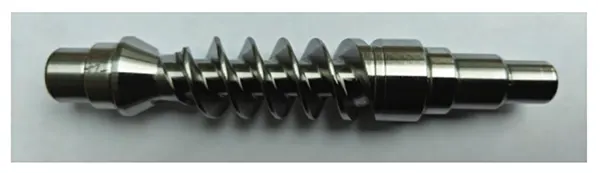
The involute worm gear serves as the core torque-transmitting part of C-EPS.
(see Figure 1) It must meet strict IT7 machining precision standards. If the tooth profile error exceeds 0.01 mm, adverse effects will appear.
This defect readily causes steering delay or abnormal noise during operation. At the same time, it must meet the efficiency demands of large-scale mass production.
There are three major pain points in current worm gear machining processes:
① The traditional turning and grinding process has low machining efficiency, with single-shift output falling short of 500 pieces.
② The hobbing and rolling process suffers from poor tooth profile consistency;
It relies on the precision of the hob, and errors can fluctuate by as much as ±0.02 mm once the tool wears down.
③ Conventional milling processes fail to meet surface finish requirements, with a surface roughness value of Ra ≥ 1.6 μm.
C-EPS worm gear machining technology needs both high precision and high efficiency.
The research and development of such technology carries important practical value.
It helps improve the market competitiveness of C-EPS products.
Efforts to improve the machining accuracy of worms have largely relied on high-end equipment, such as the CNC worm grinding machine developed by Germany’s KAPP.
Using thermal error compensation technology, this machine controls the cumulative error of the helix within 0.005 mm;
However, the cost of a single unit exceeds 8 million yuan, making the investment threshold extremely high.
Research in China has primarily focused on process optimization.
Some automakers have adopted a combination of rolling and roll-forming processes to achieve mass production of worms;
However, the machining accuracy only reaches IT8 grade, making it difficult to meet the requirements for high-end vehicle models.
Existing research has not yet established an integrated machining solution that combines “high-efficiency rough machining with high-precision finish machining.”
This paper adopts the combined process of whirl milling and profile grinding. This research constructs a comprehensive optimization system.
The system covers equipment, cutting tools, and process parameters. This research fills the technical blank of high-efficiency and high-precision machining for C-EPS worms.
Researchers employ three mainstream processes for machining worm tooth profiles.
They are turning + grinding, hobbing + roll forming, and whirl milling + grinding.
Researchers conducted a quantitative comparison among the three processes.
The evaluation indicators include surface roughness, accuracy grade and tooth profile consistency.
Machining efficiency and tool change time are also taken as production indicators.
Table 1 shows a comparison of the core metrics for the different processes, and Table 2 shows a comparison of their efficiencies.
| Process Type | Surface Roughness (Ra, μm) | Accuracy Grade | Tooth Profile Consistency | Cost Level |
|---|---|---|---|---|
| Turning + Grinding | 3.2–6.3 | IT8–IT9 | Vibration easily occurs during machining, resulting in an accuracy variation of ±0.03 mm. | Medium |
| Hobbing + Rolling | 1.6–3.2 | IT7–IT8 | Depends on the accuracy of the rolling tool; after tool wear, the machining error reaches ±0.02 mm. | High (requires dedicated equipment) |
| Milling (Whirl Milling) + Grinding | 0.4–0.8 (after milling) | IT6–IT7 | Multi-insert form milling achieves a machining error of ±0.004 mm. | Low |
| Process Type | Machining Characteristics | Output per Shift (Parts/8 h) | Changeover Time (min) | Efficiency Advantage |
|---|---|---|---|---|
| Turning + Grinding | Multiple tool retractions and manual tool changes | 80–120 | 40–60 | Baseline (1×) |
| Hobbing + Rolling | Continuous rolling process; requires a dedicated gear rolling machine | 600–800 | 90–120 | 5–8× higher than turning |
| Milling (Whirl Milling) + Grinding | High-speed cutter disc enables one-pass machining with automatic indexing | 900–1200 | 15–20 | 10–13× higher than turning, with greater changeover flexibility |
Table 2. Efficiency Comparison of Different Machining Processes
Note: Single-shift output is based on actual measurements using a φ30mm×120mm worm gear, and the equipment is a single-spindle configuration.
As shown in Tables 1 and 2, the milling + grinding process (cyclone milling for roughing/semi-finishing + fine grinding) significantly outperforms other options in terms of key machining metrics and production efficiency.
Furthermore, it eliminates the need for a dedicated gear hobbing machine, reducing machining costs by approximately 40%.
Therefore, this paper focuses on this process for further in-depth research.
As a roughing and semi-finishing process for worms, the machining accuracy and efficiency of milling directly determine the reference quality and production cycle of the subsequent fine grinding process.
This study conducts optimization design in five areas: equipment selection, clamping methods, cutting tool parameters, cooling systems, and process parameters.
(1) Selection of a High-Precision CNC Whirl Milling Machine:
Engineers select a CNC whirl milling machine fitted with high-precision feed and spindle systems to satisfy IT7 precision requirements.
The key technical parameters are as follows.
1) Feed System: Resolution ≤ 0.0001 mm; positioning accuracy over the full stroke is ±0.002 mm.
2) Spindle System: Radial runout ≤ 0.001 mm, axial runout ≤ 0.0005 mm, and speed stability of ±5 r/min.
Test data demonstrate that the machine tool achieves a positioning accuracy improvement from ±0.01 mm to ±0.002 mm.
Machinists reduce the cumulative helix error of the worm from 0.025 mm to 0.008 mm.
This improvement directly elevates the machining accuracy by two grades.
(2) Machine Tool Rigidity Enhancement Plan: Insufficient machine tool rigidity can easily cause cutting vibrations, leading to an increase in worm tooth direction error of more than 30%.
Machine tool rigidity can be improved through the following two measures.
1) Foundation Fixation: A machine tool base made of C30 concrete with a thickness of ≥500 mm is used, rigidly connected to the floor via M30 expansion bolts, with the base levelness controlled within 0.02 mm/m.
2) Structural Optimization: An inclined wedge-type locking mechanism at the connection between the tool holder and the bed increases the contact area by 40% and improves the machine tool’s static rigidity to 250 N/μm.
(1) Precision Control of Hydraulic Clamping:
Traditional manual clamping can result in axial positioning errors of up to ±0.1 mm, leading to significant fluctuations in the axial positional accuracy of the worm gear profile.
Operators control the clamping positioning error within ±0.03 mm by adopting a hydraulic self-centering chuck with a clamping force of 5–8 kN, combined with the end-face positioning reference and an axial thrust ring.
This improves the axial positional accuracy of the worm by a factor of 3, providing a stable machining reference for subsequent precision grinding operations.
(2) Improved Efficiency of Automatic Loading and Unloading:
Engineers replaced manual operation with a gantry robot to implement automatic loading and unloading of worm gears and cut the clamping time from 20 seconds per workpiece to 5 seconds per workpiece.
Engineers boosted equipment utilization from 65% to 90% and lifted single-shift output by over 300 workpieces.
Manufacturers produce C-EPS worm gears using high-quality alloy steel.
Machinists achieve a hardness of 28–32 HRC for the workpieces after quenching and tempering.
Based on the characteristics of this material, we have conducted research on cutting tool material selection, geometric parameter optimization, and wear control design during installation.
(1) Cutting Tool Material Selection:
A comparison of the cutting performance of high-speed steel (W18Cr4V), standard cemented carbide (WC-Co), and ultra-fine coated cemented carbide (YBG series) is shown in Table 3.
Engineers selected YBG ultra-fine coated cemented carbide as the substrate of the cutting tool after a comprehensive evaluation.
This cutting tool features a WC–Co matrix with Nb additions and a 3–5 μm-thick TiAlN nanocoating.
The coating hardness reaches 3,200 HV, and its red hardness can withstand temperatures up to 800°C, meeting the process requirements for high-speed cutting.
(2) Optimization of Cutting Tool Geometric Parameters:
This research takes the involute tooth profile characteristics of the worm into consideration.
Engineers specially design geometric parameters for two types of form cutters.
They are the roughing cutter (ZA-type form cutter) and finishing cutter (ZI-type form cutter) (see Table 4).
The design realizes balanced performance among cutting force, cutting edge strength and machined surface quality.
(3) Tool Installation and Wear Monitoring:
Tool installation and wear monitoring must comply with the following technical requirements.
| Tool Material | Cutting Speed (m/min) | Tool Life (Measured by Number of Workpieces Machined) | Workpiece Surface Roughness (Ra, μm) |
|---|---|---|---|
| High-Speed Steel (HSS) | ≤100 | 20–30 | 3.2–6.3 |
| Conventional Cemented Carbide | ≤200 | 50–60 | 1.6–3.2 |
| YBG Ultra-Fine Coated Cemented Carbide | 300–400 | 100–120 | 0.4–0.8 |
Table 3. Comparison of Cutting Performance of Different Cutting Tool
Note: The cutting conditions are a feed rate of 0.15 mm/r and a depth of cut of 1.2 mm.
| Parameter | Roughing Tool (ZA Type) | Finishing Tool (ZI Type) | Design Rationale |
|---|---|---|---|
| Tooth Profile Included Angle, θ (°) | 35 ± 3 | 40 | The roughing tool reduces cutting force, while the finishing tool matches a normal pressure angle of 20°. |
| Radial Rake Angle, γf (°) | 1–3 | 2–4 | Balances cutting sharpness and cutting-edge strength. |
| Radial Clearance Angle, α₀ (°) | 10–11 | 12–15 | Reduces friction and suppresses heat buildup. |
| Tool Nose Radius, rₑ (mm) | 0.2 | 0.2 | Improves heat dissipation and enhances resistance to micro-chipping. |
Table 4. Dedicated Cutting Tool Geometric Parameter Design
1) Cutter Head Configuration:
A precision cutter head with a dynamic balance accuracy of G2.5 is used.
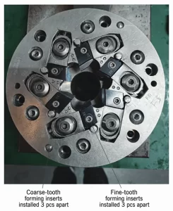
As shown in Figure 2, the cutter head is configured with three roughing cutters and three finishing cutters spaced across the six cutting positions.
Engineers set the roughing cutters to extend 0.12–0.20 mm beyond the finishing cutters, allowing operators to complete roughing and semi-finishing in a single pass.
2) Helix Angle Matching:
The swiveling cutter head is used to align the tool’s helix angle with the worm’s lead angle γ.
The formula for calculating the lead angle is:

where γ is the lead angle (°); PZ is the axial lead (mm); and d1 is the pitch circle diameter (mm).
3) Wear Monitoring:
Use a worm gear tester to monitor tooth profile errors in real time.
Replace the tool promptly when wear reaches 0.005 mm.
The cutting inserts can be reused 3 or 4 times after regrinding.
(1) High-Pressure Aerosol Cooling Design:
The cutting linear speed of the spiral milling process reaches 260–360 m/min, with temperatures in the cutting zone reaching as high as 600–800°C.
Engineers employ a 0.80–1.38 MPa high-pressure air-mist cooling system and adopt a blend of 5% extreme-pressure emulsion and compressed air as the cooling medium.
The mixed coolant flows toward the cutting area.
Four symmetrically arranged fan-shaped nozzles with a diameter of φ1.5 mm are used for delivery.
Compared with conventional splash cooling, the cooling efficiency rises by 60%.
Meanwhile, the chip residue rate is lowered to less than 0.5%.
(2) Optimization of Milling Parameters:
Researchers adopt the orthogonal experimental design method to determine the optimal combination of worm gear milling process parameters and balance machining efficiency and quality.
1) Cutting Depth: The total cutting depth for gear milling is calculated based on the full tooth height h.

In the formula, h is the total tooth height (mm), which is the total depth of cut for the milled tooth;
d₁ is the pitch circle diameter of the gear (mm); mx is the axial module (mm);
The “2” in 2mx represents the multiplier corresponding to the tooth top height coefficient; the standard tooth top height is 1mx, so the value on both sides is 2mx;
2.4 is the tooth root height coefficient; the standard tooth root height is 1.2mx, so the value on both sides is 2.4mx.
2) Feed rate: The feed rate is 0.13–0.20 mm/r, dynamically adjusted based on material hardness.
3) Speed: The workpiece spindle speed is 12–18 r/min, and the cutter head speed is 6,000–8,000 r/min (cutting linear speed is 300–400 m/min).
4) Finishing allowance: The finishing allowance is 0.5–0.7 mm to balance grinding efficiency and final machining accuracy.
Using the above parameters, the production cycle of a single cyclone milling machine reaches 90–105 pieces/h.
After milling, the surface roughness (Ra) of the worm is 0.8–1.2 μm, and the tooth profile error is ±0.004 mm.
Grinding is the finishing process for C-E P S worms and directly determines the final machining accuracy of the worm.
This study addresses process control from two aspects—the selection of grinding equipment and grinding wheels, and the control of grinding parameters and cooling—to ensure that the worm consistently achieves IT7 accuracy.
Engineers select a CNC worm gear grinding machine with automatic tooth alignment.
The machine has a positioning accuracy of ±0.001 mm.
Engineers adopt the form grinding method and utilize a CNC dresser to dress the grinding wheel into an involute profile matching the worm gear, which guarantees consistent tooth profile machining.
The grinding wheel selected is a white corundum (WA) wheel with a hardness of H5, grit size F80, and a resin bond (offering excellent impact resistance).
The wheel has a diameter of 405 mm and an operating linear speed of 45 m/s.
White corundum grinding wheels possess good self-sharpening properties, effectively reducing the generation of grinding heat.
They generate less grinding heat than silicon carbide wheels, thereby preventing grinding burn on the workpiece.
Engineers determine the optimal grinding process parameters as follows, according to the reference surface formed after worm milling and the final accuracy requirements.
1) Speed: The workpiece spindle speed is 5–8 r/min, and the grinding wheel speed is 1800–2000 r/min (grinding wheel linear speed is 2289–2543 m/min).
2) Feed Rate: The rough grinding feed rate is 180–200 mm/min, and the finish grinding feed rate is 50–80 mm/min.
3) Grinding wheel dressing cycle: Dress the grinding wheel after every 5–8 worm grinding operations to ensure the grinding wheel’s form accuracy.
An extreme-pressure cutting oil with a viscosity of 20–30 mm²/s at 40°C is used as the cooling medium.
Forced cooling is achieved via a 2 MPa high-pressure oil pump, with a cooling medium flow rate of ≥50 L/min.
This ensures adequate cooling of the grinding zone while simultaneously removing grinding chips to prevent abrasive grain clogging, which could affect machining quality.
Researchers adopted a high-precision worm inspection system for verification.
Worms processed by the optimized form grinding process have stable performance.
Their tooth profile accuracy steadily reaches the IT7 level.
The surface roughness (Ra) ranges from 0.2 μm to 0.4 μm. The helix angle error is controlled within ≤0.008 mm.
The production cycle per machine is 60–72 pieces per hour, meeting the process requirements for large-scale mass production of C-E P S worm gears.
Note that the dressing profile and shape retention of the grinding wheel are critical control points in the grinding process.
Any deviation in the grinding wheel’s shape will directly result in the worm’s helix angle and tooth profile errors exceeding the specified limits;
Therefore, grinding wheel dressing and inspection must be performed in strict accordance with process requirements.
Multidimensional optimization was carried out on processes and parameters.
This study builds an efficient and high-precision machining technology system.
The system is used for the tooth profile machining of C-EPS worms. Several core research conclusions are obtained as follows.
1) Cyclone milling for roughing/semi-finishing combined with form grinding was determined to be the optimal machining process for C-EPS worms.
Compared to the traditional turning and grinding process, this method increases efficiency by 10 to 13 times, achieves a machining accuracy of IT7, and reduces machining costs by approximately 40%.
2) We proposed a stiffness enhancement plan and hydraulic clamping strategy for high-precision CNC whirl milling machines, increasing the machine’s static stiffness to 250 N/μm and reducing clamping positioning error from ±0.1 mm to ±0.03 mm.
3) Developed YB G ultra-fine-coated cemented carbide cutting tools suitable for alloy steel worms, along with a 0.80–1.38 MPa high-pressure aerosol cooling system, enabling high-speed cutting at 300–400 m/min and achieving a post-milling surface roughness value of Ra ≤ 0.8 μm.
4) By optimizing form grinding process parameters and setting the grinding wheel dressing cycle to 5–8 parts, the post-grinding surface roughness (Ra) of the worm was reduced to 0.2–0.4 μm, with a helix angle error of ≤0.008 mm; the resulting precision and stability meet mass production requirements.
Artificial intelligence technology can be integrated in follow-up research.
It aims to realize intelligent machining of C-EPS worms. A machine vision system can monitor tool wear in real time.
Deep learning models can be used to dynamically adjust cutting parameters.
Thermal error compensation algorithms for machine tools can be developed.
These measures will further lift worm grinding accuracy to IT6 grade.
The research can offer technical support for the development and manufacturing of high-end C-EPS products.
It also helps expand the market application range of related products.

