How to efficiently machine shaped parts on CNC mill-turn machines?



The guide sleeve is a critical component within a diesel engine’s high-pressure fuel pump. This component acts as a transmission element between the cam and the plunger.
It converts the lateral thrust generated by the cam into an axial force acting on the plunger.
This force pushes the plunger to move upward along its axis. The upward movement enables the plunger to pressurize fuel.
At the same time, it limits the rotational travel of the plunger during fuel flow regulation.
As such, it performs the key functions of fuel pressurization and flow regulation, and its precision directly affects the overall performance and stability of the diesel engine.
For a certain type of diesel engine guide sleeve, the groove surfaces, radial holes, and their relative positional accuracy require high precision.
Operators clamp the workpiece with an indexing head and a chuck on vertical machining centers.
They conduct finish machining on both groove surfaces and radial holes concurrently to satisfy relevant positional accuracy specifications.
However, this process requires aligning and clamping each part individually, resulting in low clamping efficiency.
Furthermore, due to the part’s structural limitations, the clamping area is short, resulting in unstable clamping and low clamping accuracy.
This makes it difficult to consistently meet the product drawing specifications, leading to a high rate of out-of-tolerance parts.
There is now an urgent need to design a milling fixture that improves clamping efficiency and accuracy, while meeting the product drawing requirements.
The structure of the guide sleeve is shown in Figure 1.
The part is made of 40CrNiMoA alloy structural steel with a hardness of 40–44 HRC. The main challenges are as follows.
1) The spatial positioning of the groove surfaces relative to the part’s outer circumference is highly precise.
Engineers define the Y-axis plane using the radial hole axis and the part’s central axis.
The distance between the part’s axis and the intersection lines formed by the four groove surfaces and this Y-axis plane measures (5.9 ± 0.05) mm.
2) Distance from the bottom plane of the groove to the right end face is (38.3 ± 0.02) mm, which is a stringent requirement.
3) Positional requirements for the radial hole relative to the part’s outer circumference and the groove surfaces are quite stringent:
The radial hole’s symmetry relative to the outer circumference is 0.05 mm, and the angle between the radial hole’s axis and one of the groove surfaces is 42° ± 6′.
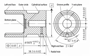
Referring to Figure 1 and the relevant technical requirements, the part’s primary reference is the outer circle, and the axial reference is the right end face.
The fixture’s positioning references should coincide with the design references as much as possible;
Machinists locate the part’s center by referencing its outer cylindrical surface and determine the axial length using the right end face.
The challenge with the fixture lies in the lack of a suitable clamping position.
Conventional approaches involve clamping the part’s left end face or the outer circle, but these present the following issues.
1) If machinists clamp the part at its left end face, the thin wall thickness at this position makes the workpiece susceptible to deformation caused by clamping forces.
Machinists may observe part springback after finishing machining and releasing the clamping plate, which readily triggers deviations from the (5.9±0.05) mm tolerance.
2) If machinists clamp the workpiece by its outer diameter, the clamping process applies radial forces to the part without exerting axial clamping force.
Consequently, the part’s right end face cannot effectively contact the fixture’s locating surface, which can easily result in a deviation of (38.3 ± 0.02) mm.
Engineers can select the right-side conical surface as the clamping position after analyzing the structural characteristics of the part.
By clamping the conical surface, the thin-walled area of the left end face is not subjected to clamping force, eliminating the risk of deformation due to clamping stress.
Meanwhile, the clamping mechanism applies an axial clamping force to the part.
This ensures effective contact between the right end face and the fixture locating surface.
As a result, this design solves both of the aforementioned problems.
Operators must position the clamping plate to evade the radial hole; designers also need to ensure the fixture maintains good operability.
Engineers designed an innovative milling fixture, illustrated in Figure 2, based on the above analysis.
This fixture features an ingenious design, a compact structure, and is simple and convenient to use.
At the same time, it minimizes clamping errors and effectively ensures the geometric accuracy of the workpiece. The fixture
consists of a clamping body 1, two clamping plates 2, a clamping screw 3, two connecting shafts 4, two screw pins 5, and two nuts 6.
Operators insert the workpiece’s outer circumference into the positioning hole of the clamping body when operating the fixture.
Turning the clamping screw with a wrench drives the connected connecting shafts; at this point, the two connecting shafts move either simultaneously inward or outward.
The connecting shafts drive the two clamping plates. The clamping plates rotate around their respective screw pins.
The clamping ends on the front of the two clamping plates move synchronously.
They either clamp or release the workpiece at the same time. This mechanism realizes clamping and unclamping operations of the part.
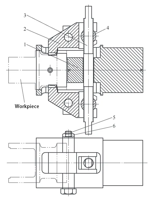
1-Clamping body 2-Pressure plate 3-Clamping screw 4-Connecting shaft 5-Screw pin 6-Nut
To facilitate understanding, this section briefly introduces the structure of the main components of the milling fixture, the assembly steps, and precautions for use.
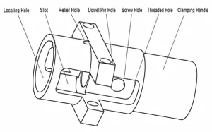
As shown in Figure 3, the clamping body features a locating hole at one end, with a locating clearance of 0.005–0.020 mm relative to the workpiece’s outer diameter, used for positioning the workpiece;
Designers fit a clamping handle on the other end to secure the workpiece within a chuck during machining operations.
The central section incorporates a threaded hole, and a 0.3 mm clearance separates the hole from the clamping screw.
This clearance enables the clamping screw to pass through horizontally. The screw can fix the workpiece at the designated position.
Machinists machine two symmetrical grooves on the outer circumference so the clamping end of the clamping plate can pass through and fasten the workpiece.
Designers arrange two sets of pin holes for mounting set screws.
They also incorporate a clearance hole to facilitate the machining of radial holes on the part.
The surface of the clamping body undergoes nitriding treatment to form a nitrided layer, which increases surface hardness, thereby enhancing wear resistance and extending its service life.
There are two clamping plates, one on the left and one on the right.
The central portion of each is pivotally connected to a screw pin mounted on the clamping body;
Designers equip each plate with a clamping end at the front and mount its rear end onto the corresponding connecting shaft on the matching side.
The connecting shafts drive the plates to rotate around their respective screw pins.
The clamping screws have left-hand and right-hand threads at their respective ends.
There are two connecting shafts, one on the left and one on the right, which are connected to the left-hand and right-hand threads at both ends of the clamping screw, respectively.
The clamping screw drives them to move simultaneously inward or outward.
Assembly steps for the milling fixture:
Due to structural limitations, the design travel range for the two clamping plates to open outward and retract inward is relatively small.
The two connecting shafts have a specific installation spacing.
If this spacing is excessively large or small, problems will occur.
After the clamping plates swing outward, they cannot properly surround the workpiece.
Or when the clamping plates retract inward, they are unable to hold the workpiece firmly.
In such cases, follow Step 2 above to readjust the connecting shafts to the appropriate position to ensure the correct installation spacing.
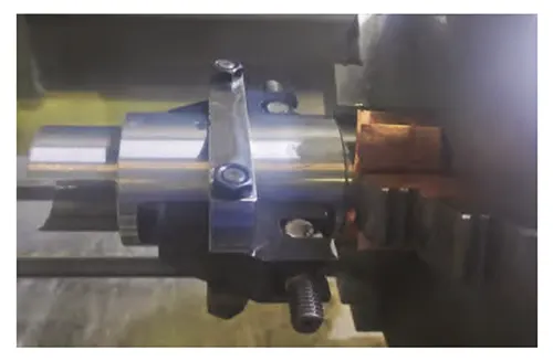
During use, as shown in Figure 4, first clamp the fixture’s clamping handle onto the indexing head’s chuck, and use a dial indicator to align the fixture’s front end so that its radial runout is within 0.01 mm.
Operators place copper shims on the chuck jaws if alignment fails.
They then use a dial indicator to verify that the front and side reference lines of the fixture run parallel to the machine tool’s X-axis within a tolerance of 0.01 mm.
Use the dial indicator to level the flat surface of the fixture and determine its circumferential position;
At this point, the fixture is precisely mounted on the chuck.
Insert the outer diameter of the workpiece into the positioning holes of the fixture body.
A right-angle square is used at the same time for alignment.
The reference is the rough-machined grooved surface from the previous working procedure.
This operation defines the circumferential position of the workpiece.
Finally, use a wrench to tighten the clamping screws. After the part is securely clamped, start the machine tool program to begin machining.
Practical machining verification demonstrates that this fixture delivers stable and reliable performance.
After machinists process workpieces with the fixture, the finished parts consistently satisfy all requirements specified in product drawings.
Compared to the original chuck clamping method, it offers the following advantages:
① There is no need to use a dial indicator to align and clamp each workpiece, which significantly reduces clamping difficulty and shortens clamping time from the previous 3–5 minutes to approximately 1 minute.
② Clamping accuracy and stability have been greatly improved, with the dimensional out-of-tolerance rate dropping from approximately 20% to within 1%.
The positional accuracy deviations of diesel engine guide sleeve groove surfaces and radial holes were investigated.
These deviations occur after precision machining operations.
Relevant research and analysis work has been conducted on these issues.
Based on the research findings, this paper proposes an innovative milling fixture design.
The original chuck existed obvious drawbacks. Its clamping accuracy was insufficient and machining efficiency was low.
This new design successfully solves the above problems. Accordingly, the machining quality and production efficiency are greatly improved.
The findings hold considerable reference value and can serve as a guide for the design of fixtures for similar parts, making them highly applicable for wider adoption.

