What impact does CNC tool selection have on the CNC machining process?


Ti-6Al-4V (TC4) is an alloy characterized by high specific strength, excellent toughness, and resistance to high-temperature environments.
Engineers widely use it across core industrial sectors, such as aerospace, medical devices, transportation, and precision measuring equipment, providing critical support for technological advancements in these fields.
Manufacturers can use it to produce high-strength casings, support frames, exhaust systems, thermal insulation layers, and heat-resistant skin.
This capability significantly drives rapid advances in aerospace technology. Manufacturers classify titanium alloys such as forged and cast types based on manufacturing processes.
During machining, they generate high cutting forces and temperatures, which can easily cause tool vibration and severe surface wear; Therefore, they are considered difficult-to-machine materials.
Building on previous research, this paper investigates the principal cutting forces during high-speed milling of TC4 alloy and enhances parameter optimization analysis;
The findings hold significant practical implications.
We used titanium alloy plates as the substrate and carried out laser cladding with a Lasertel laser.
We set these processing parameters: power at 3250 W, scanning speed at 5 mm/s, spot size at 12 mm × 3 mm, powder bed thickness at 3 mm, cladding layer spacing at 0.6 mm, and 285 mm between the laser head and the cladding surface.
Researchers used argon gas for protection and successfully prepared TC4 specimens.
They then carried out cutting experiments.
Researchers machined the test specimens to dimensions of 50 mm × 40 mm × 40 mm via precision wire cutting and secured them with precision fixtures to ensure controllable cutting force distribution.
Researchers installed a Kistler 9265B piezoelectric sensor in the system to measure cutting forces in real time during high-speed milling.
The principal cutting force (Ft), as the maximum force acting along the milling cutter’s trajectory, is crucial to the entire cutting process;
Therefore, this study conducted an in-depth analysis of the various factors influencing this key parameter.
The process conditions for the milling tests in this experiment are as follows:
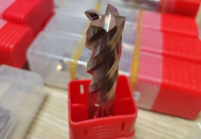
The milling machine is a FANUC-D14MiA vertical machining center; the cutting tool is a Walter WMG40 carbide end mill with a diameter of 20 mm;
The tool parameters are a front angle of 12°, a back angle of 14°, helix angle of 35°, milling speed of 100–800 mm/min, feed rate of 0.02–0.10 mm/r, and cutting depth of 0.4–1.2 mm.
Researchers performed single-tooth cutting tests to compare how factors including cutting speed, depth, and feed rate affect cutting forces.
Figure 1 shows the results obtained by applying two methods to the various milling directions set for this experiment;
It can be seen that the cutting forces have changed.
Experimental studies indicate that the material surface exhibits isotropic characteristics during milling, and when milling along the same path, the principal cutting force exceeds 90°.
This is because, during the additive manufacturing process, most of the heat is generated by laser irradiation. Under laser irradiation, overlapping layers form on the coated surface.
As the laser spot advances, the crystal temperature undergoes drastic changes.
Under the set temperature gradient, the microstructure of the alloy also undergoes significant changes, thereby altering the alloy’s mechanical properties.
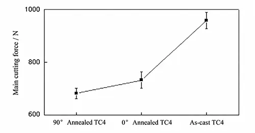
Figure 2 shows the variation in the principal cutting force of titanium alloy under different single-tooth feed rates, with a set cutting speed of 400 mm/min and a milling depth of 0.8 mm.
As the feed rate increases, the titanium-based composite material generates greater principal cutting forces.
This is because an increased single-tooth feed rate causes each cutting edge to produce a thicker chip and remove more unmachined material, thereby significantly increasing cutting resistance.
Due to the milling cutter’s helical geometry, multiple cutting edges produce a chip-ejection effect during the milling process.
During machining, as the depth of cut at the tool edge increases, larger principal cutting forces are generated.
Milling tests on two different types of titanium-based materials can determine the performance parameters indicating the lowest load when the principal cutting force is applied in the 90° milling direction.
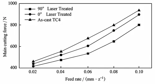
Figure 3 shows the main cutting force data obtained from tests conducted at different milling depths, with a set milling speed of 200 mm/min and a feed rate of 0.06 mm/z.
The results indicate that the main tangential force increases linearly as the machining depth increases.
This is because, as the milling depth increases, the tool must resist greater energy, and the resistance at the cutting edge also increases significantly.
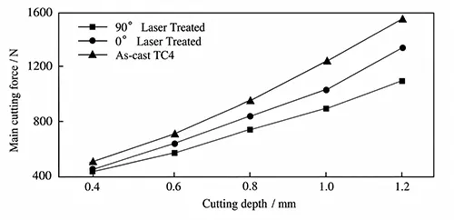
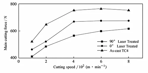
Figure 4 shows the results for the principal cutting force at different milling speeds (milling depth: 0.04 mm).
When the milling speed is below 400 m/min, the principal cutting force increases significantly as the speed rises; beyond this value, it tends to stabilize.
The experimental results indicate that appropriately increasing the cutting speed helps optimize the machinability of titanium alloys.
This paper analyzes the principal cutting forces during high-speed milling of TC4 alloy subjected to laser cladding and optimizes the process parameters.
The material surface exhibits unidirectional characteristics;
When milling along the same path, the principal cutting force exceeded 90 N, indicating significant cutting forces.
As feed rate, cutting depth, and cutting speed increased, the principal cutting force also increased.
Further surface inspections are needed to verify the effectiveness of the optimized parameters.